
Circuit and method for recovering a carrier

Inactive Publication Date: 2006-03-30
ENTROPIC COMM INC
View PDF46 Cites 7 Cited by
  • Summary
  • Abstract
  • Description
  • Claims
  • Application Information

AI Technical Summary

Benefits of technology

[0014] The residual phase error is used to augment recovery of the carrier such that demodulation can be implemented without disturbance even in the case of signal changes outside the PLL bandwidth, or at least be implemented in a significantly improved manner.

Problems solved by technology

However, if the received signal contains components lying outside the PLL bandwidth, a residual phase error remains.
This error causes a reduction in the level of demodulation, thereby causing the signal to be demodulated incorrectly.
The disadvantage is thus that error-free demodulation cannot be effected due to this residual phase error.
These delays are often called dead times in control engineering and reduce the maximum possible loop gain and thus the speed of the control loop.
If in this case an excessively high loop gain is selected, the control loop becomes unstable.
Since in this circuit the carrier recovery is not able to react quickly enough, the frequency change manifests itself as a rotation, meaning that the phase error becomes increasingly larger until the amplitude, and thus the frequency, change back to the original state.
For a connected television set, these distortions of the synchronization pulses mean that the horizontal alignment of the scanning lines cannot be precisely determined—with the resulting distorted picture contents.

Method used


Image

  • Circuit and method for recovering a carrier
  • Circuit and method for recovering a carrier
  • Circuit and method for recovering a carrier

Examples


Embodiment Construction

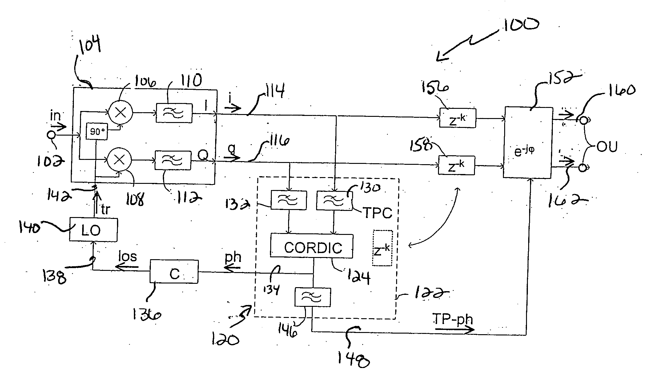
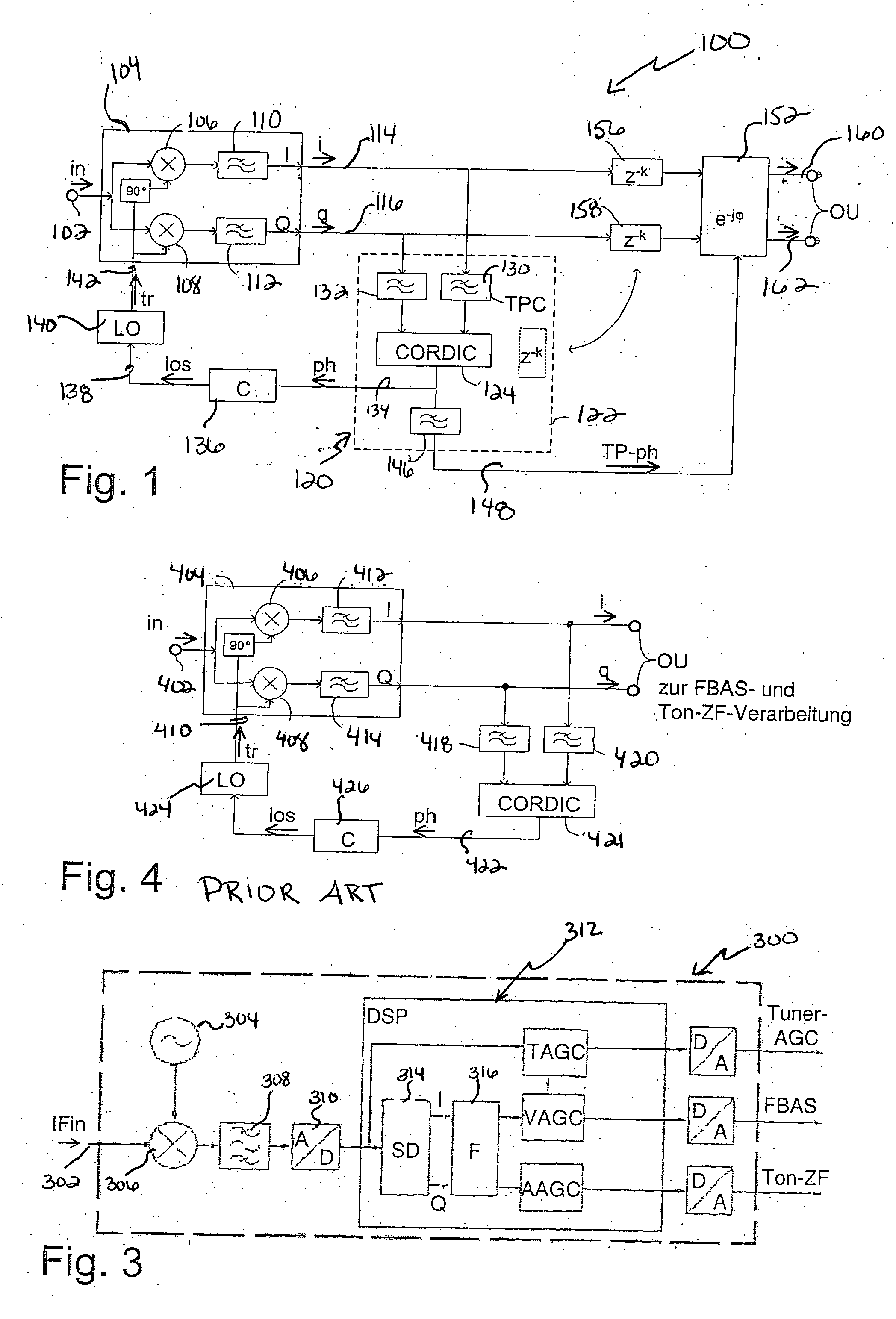
[0032]FIG. 1 illustrates a circuit 100 to effect carrier recovery of a reconstructed carrier for an input signal in, specifically, a television signal input on a line 102. The individual components described may be designed as individual and separate structural elements. Implementation is also possible in the form of an integrated circuit or software in a processor, to the extent this is feasible for the individual components.

[0033] The input signal on the line 102 is input to a mixer 104, which includes multipliers 106, 108 that generate in-phase and quadrature signal components, repectively. The in-phase and quadrature signal components are filtered by low-pass filters 110, 112, respectively and the resultant I and Q signal components are output on lines 114, 116, respectively. At each of the two second inputs of the multipliers 106, 108, a carrier signal tr is applied in the known manner such that after multiplication of the input signal by the carrier signal an in-phase and a q...


PUM


Abstract

The invention relates to recovering a carrier for a synchronous demodulator, that receives an input signal. A carrier is reconstructed for the provided input signal, and the input signal (in) and carrier (tr) are mixed to generate a mixed signal to be outputted (i, q), wherein a residual phase error of the mixed signal is corrected by a phase shift to provide a phase corrected output signal.

Description

PRIORITY INFORMATION [0001] This patent application claims priority from German patent application 10 2004 047 424.9 filed Sep. 28, 2004, which is hereby incorporated by reference. BACKGROUND OF THE INVENTION [0002] The invention relates to the field of signal processing, and in particular to recovering a carrier for a synchronous demodulator. [0003] In order to transmit a signal, especially through a wireless interface, the signal is modulated before transmission. Demodulation is implemented on the receiver side. In order to demodulate the signal using a synchronous demodulator, it is necessary to reconstruct the carrier signal or the carrier for the signal. The received signal is then mixed with this reconstructed carrier into the baseband using an I / Q mixer, and demodulated therewith. A phase-locked loop (PLL) is used to reconstruct the carrier in the process of carrier recovery. This loop measures the current phase difference between the received and reconstructed carrier to cal...

Claims


Application Information

Patent Timeline
IPC IPC(8): H04L27/22H03D3/24
CPCH03L7/0805H04L27/0014H04L2027/0057H04L2027/0046H04L2027/0032H04N7/015
Inventor STEINBACH, INGO
Owner ENTROPIC COMM INC
Learn More