Vessel-dependent flip angle modulation in tof mr angiography

Inactive Publication Date: 2010-06-10
SIEMENS HEALTHCARE GMBH
View PDF5 Cites 1 Cited by
  • Summary
  • Abstract
  • Description
  • Claims
  • Application Information

AI Technical Summary

Benefits of technology

[0009]An object of the present invention is to show vessels that do not run perpendicular to the

Problems solved by technology

Although contrast agent-intensified angiography methods have a wide range of use, contrast agents are not permitted for angiography in all countries.
Furthermore, contrast agent-intensified angiography imaging methods should not be used for examination subjects with renal insufficiency.
TOF MR angiography has the disadvantage that the contrast between vessels and s

Method used


Image

  • Vessel-dependent flip angle modulation in tof mr angiography
  • Vessel-dependent flip angle modulation in tof mr angiography
  • Vessel-dependent flip angle modulation in tof mr angiography

Examples


Example

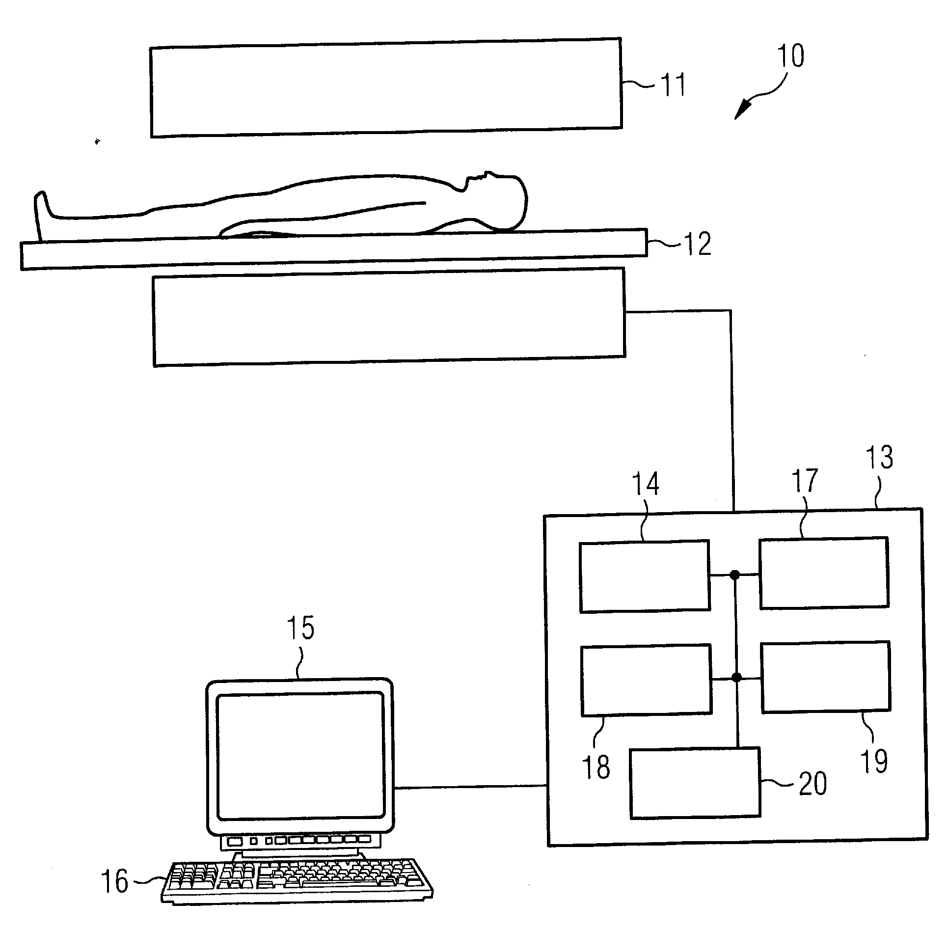
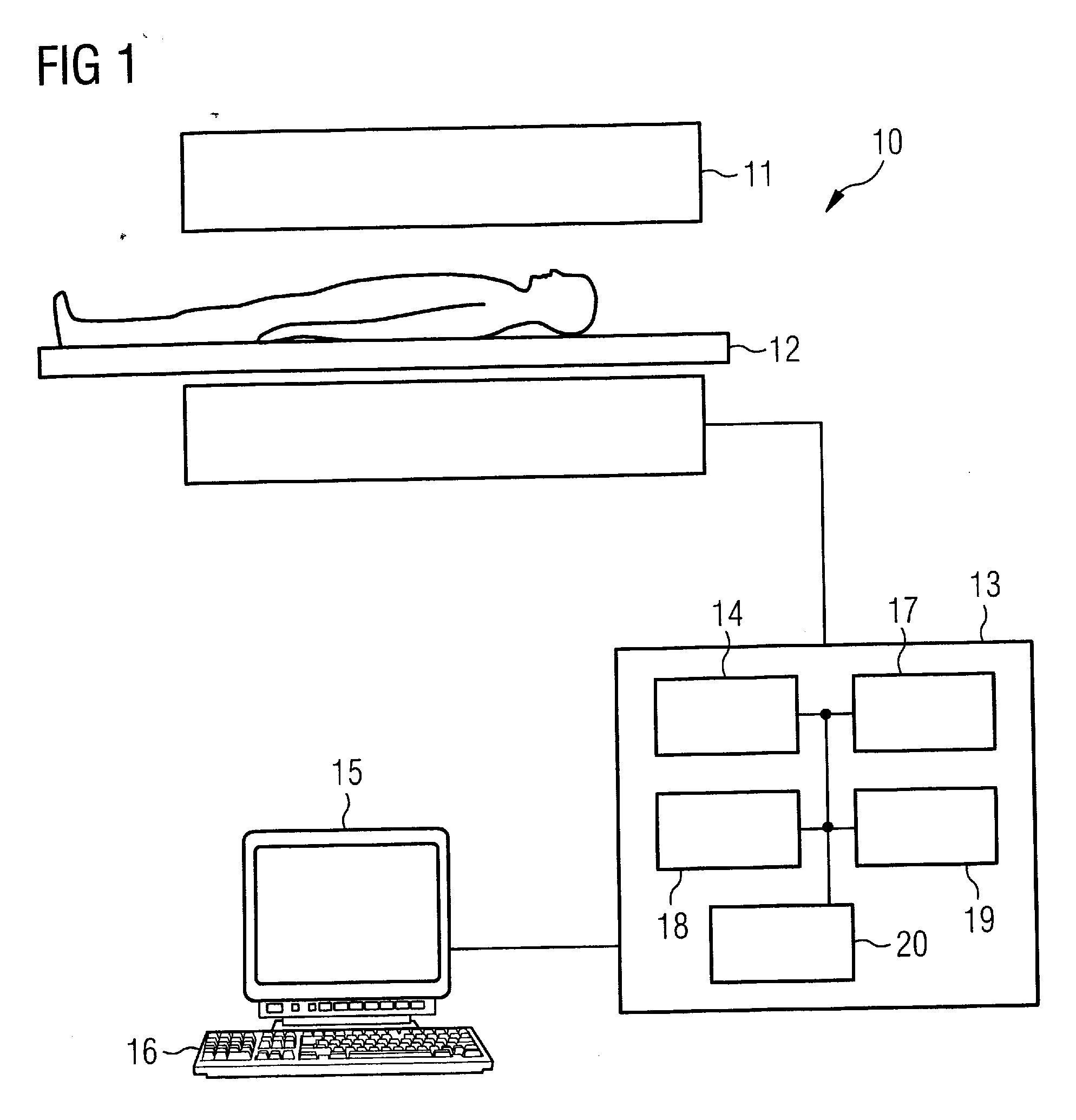
[0020]An MR system 10 that has a magnet 11 to generate a polarization field BO is shown in FIG. 1. An examination subject arranged on a bed 12 is driven into the isocenter of the magnet 11 in order to acquire MR images there. How MR images of the examination subject can be created via radiation of RF pulses and switching of magnetic field gradients is known to the man skilled in the art and is not explained in detail here. The MR system furthermore has a control computer 13 with which the MR system can be controlled. The control computer 13 has an acquisition unit 14 or image sequence control unit which has multiple RF emitter units to radiate simultaneous RF pulses. Furthermore, the acquisition unit 14 has a gradient controller to switch the temporally demarcated magnetic field gradients in connection with the RF pulses. An operator can acquire overview images of the examination subject 13 and display them on the monitor 15. The operator can then define the volume in which the TOF ...


PUM


Abstract

In a method to excite a magnetization in the generation of MR angiography images with the TOF technique, a slice plane is determined in which the magnetization for the generation of the MR angiography images should be excited, a position of a vessel in the slice plane is determined, and the magnetization is excited in the slice plane such that the magnetization in the vessel has a flip angle gradient in the direction of the vessel.

Description

BACKGROUND OF THE INVENTION[0001]1. Field of the Invention[0002]The present invention concerns a method for excitation of a magnetization in the generation of MR angiography images with the TOF (time-of-flight) technique, and an MR system for implementing such a method.[0003]2. Description of the Prior Art[0004]Time-of-flight magnetic resonance angiography (TOF MR angiography) is a non-invasive imaging method for depiction of the vessel structure of an examination subject. It is based on the inflow of “fresh” spins, which have not been pre-saturated, into an imaging plane or, respectively, into an imaging volume. The stationary magnetization, i.e. the stationary spins of the imaging plane, is saturated by the repeated excitation in a short time interval TR. The signal of this magnetization is largely suppressed while the magnetization that has not been pre-saturated (which results via the blood flow into the imaging plan during the acquisition, for example) exhibits a high signal pr...

Claims


Application Information

Patent Timeline
IPC IPC(8): A61B5/055G06K9/00
CPCA61B5/02007A61B5/055G01R33/5635G01R33/5601G01R33/4835
Inventor FAUTZ, HANS-PETER
Owner SIEMENS HEALTHCARE GMBH
Why Eureka
Try Eureka