Spinal fixation tool attachment structure

a technology of attachment structure and tool, which is applied in the field of spinal surgery apparatus and methods, can solve the problems of additional invasive trauma, large tool weight, and oversized or irregular surfaces or protruding, and achieve the effects of minimal surgical invasion of the patient, and easy alignment and positioning

Active Publication Date: 2006-03-30
NUVASIVE
View PDF99 Cites 228 Cited by
  • Summary
  • Abstract
  • Description
  • Claims
  • Application Information

AI Technical Summary

Benefits of technology

[0018] Therefore, the objects of the present invention are: to provide a compact tool assembly for supporting and installing bone screws and other implants with minimal surgical invasion to the patient; to provide such an assembly wherein a tool providing support and stabilization for implant engaging members of the assembly during bone screw implantation may also be utilized for deployment of rod containment tangs and as a rod reducer; to further provide a set of tools for implanting a spinal rod for support or alignment along a human spine with minimal surgical invasion of the patient; to provide such a set of tools including a pair of end tool guides for slidably guiding opposed ends of the rod toward end bone screws attached to the end guide tools; to provide such a set of tools including intermediate guide tools for each intermediate bone screw that guide the rod in slots therethrough to respective bone screws; to provide such a set of tools including rod and closure top installation tools for assisting in securing the rod in the bone screws; to provide such a set of tools wherein the guide tools are easily attached to and disengaged from the bone screws; to provide such a set of tools wherein the guide too

Problems solved by technology

Problems arise when implantation tools designed for traditional surgery that is highly invasive are utilized in percutaneous surgery.
The tools may be bulky, oversized or have irregular surfaces or protrusions.
A projecting actuator arm or fastening member may be useful with respect to the spinal screw implantation process or the rod reduction process, but there is insufficient clearance to use such structure and/or such structure may produ

Method used


Image

  • Spinal fixation tool attachment structure
  • Spinal fixation tool attachment structure
  • Spinal fixation tool attachment structure

Examples


Embodiment Construction

[0080] As required, detailed embodiments of the present invention are disclosed herein; however, it is to be understood that the disclosed embodiments are merely exemplary of the invention, which may be embodied in various forms. Therefore, specific structural and functional details disclosed herein are not to be interpreted as limiting, but merely as a basis for the claims and as a representative basis for teaching one skilled in the art to variously employ the present invention in virtually any appropriately detailed structure.

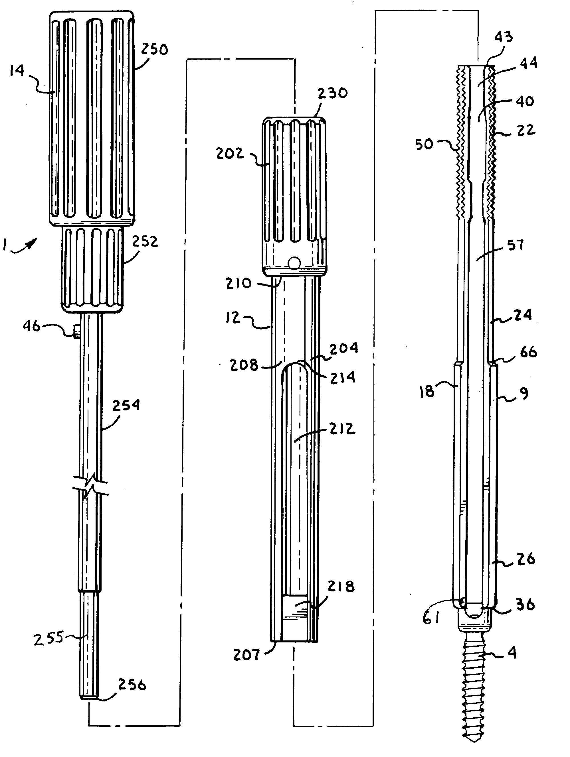
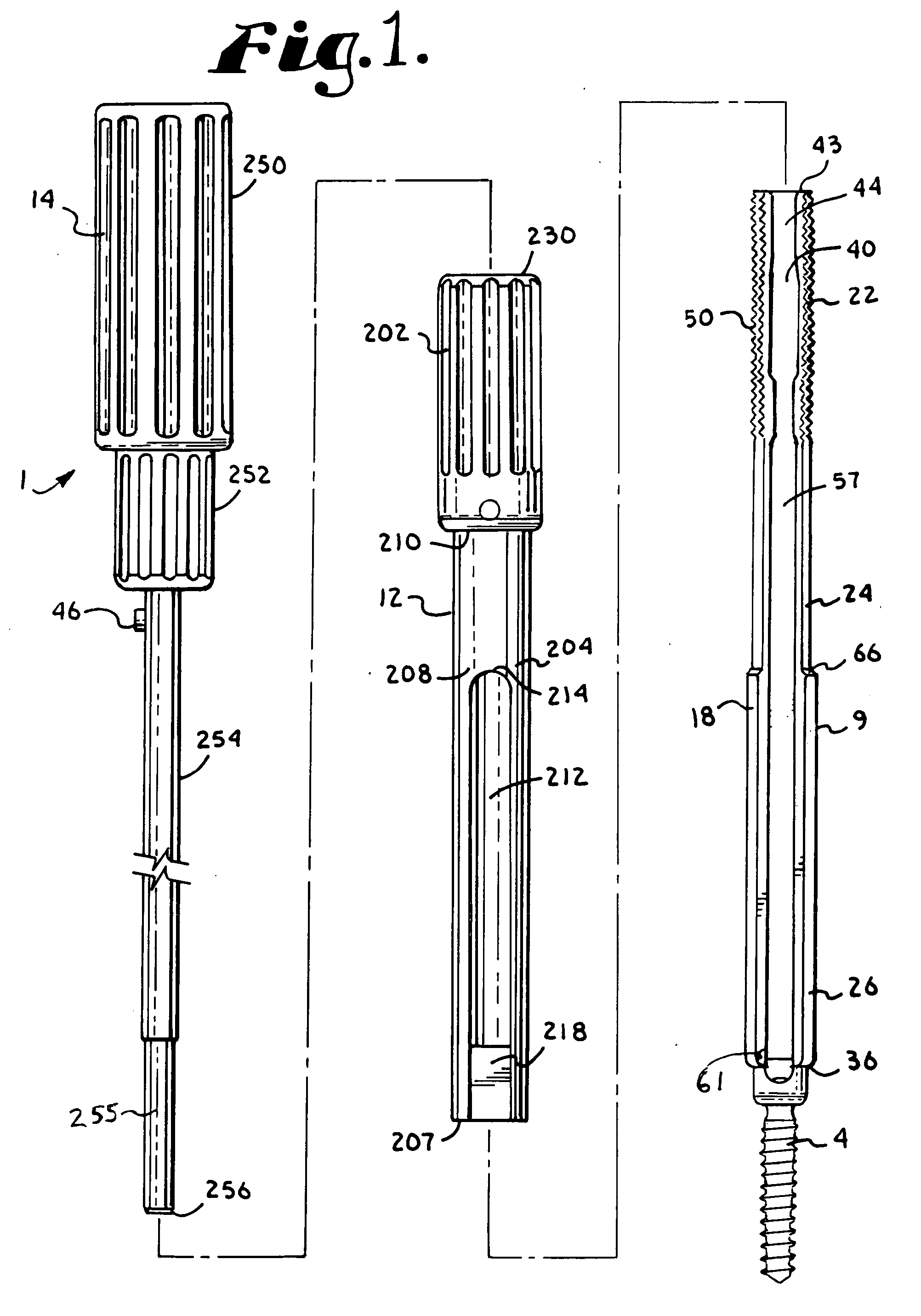
[0081] With reference to FIG. 1, and for example, also FIGS. 37 and 40, reference numeral 1 generally designates a tool assembly according to the present invention and reference numeral 2 generally designates a tool set according to the invention, made up of a number and variety of tool assemblies 1 for use in installing a set of bone screws 4 into a patient's spine 6, followed by the installation of an orthopedic spinal rod or longitudinal member 8 into th...


PUM


Abstract

A tool set for implanting bone screws in a human spine, followed by the implantation of a rod into the bone screws includes end guide tools having flexible back wall flaps that receive opposite ends of the rod and intermediate guide tools that hold the rod in intermediate locations between the end guide tools. Both the end and intermediate guide tools include an attachment structure for operably connecting the guide tool to a bone screw. The attachment structure includes an undercut and/or recess so as to resist splaying and separation of the guide tool from an attached bone screw.

Description

CROSS-REFERENCE TO RELATED APPLICATIONS [0001] This application claims the benefit of U.S. Provisional Application No. 60 / 630,536 filed Nov. 23, 2004; and is a continuation-in-part of U.S. patent application Ser. No. 10 / 996,289 filed Nov. 23, 2004; and also is a continuation-in-part of U.S. patent application Ser. No. 10 / 789,149, filed Feb. 27, 2004, all of which are incorporated herein by reference.BACKGROUND OF THE INVENTION [0002] The present invention relates to apparatuses and methods for use in performing spinal surgery and, in particular, to tools and methods of using such tools, especially for percutaneously implanting spinal screws and for implanting a rod for spinal support and alignment, using minimally invasive techniques. [0003] For many years, spinal osteosynthesis apparatuses have been utilized to correct spinal deformities, injuries or disease. In such procedures, elongate rods are surgically attached to vertebrae of the spine to provide support and / or to realign or ...

Claims


Application Information

Patent Timeline
IPC IPC(8): A61F2/30
CPCA61B17/7011A61B17/7037A61B17/7076A61B17/7091A61B17/7085A61B17/7089A61B17/7082A61B17/7038A61B2017/564A61B17/7032A61B2090/037A61B17/7008A61B17/701A61B17/702A61B17/7001A61B17/7002A61B17/7035A61B17/7086A61B17/7088
Inventor JACKSON, ROGER P.
Owner NUVASIVE
Why Eureka
Try Eureka