System for measuring characteristics of a digital signal

a digital signal and characteristic technology, applied in the field of automatic testing equipment, can solve the problems of data signal appearing jittery relative to the clock signal, random jitter, receiving ic to perceive the data signal as jittery relative,

Inactive Publication Date: 2006-03-30
CREDENCE SYSTEMS
View PDF30 Cites 51 Cited by
  • Summary
  • Abstract
  • Description
  • Claims
  • Application Information

AI Technical Summary

Benefits of technology

[0013] In accordance with the invention, rising and falling edges of the DUT output signal are detected when the DUT output signal rises above or falls below adjustable reference voltages, and one or more trigger signal edges are generated in response to selected DUT output signal edges occurring during separate repetitions of the digital signal pattern. The trigger generator can be configured to generate each trigger signal edge in response to the same or a different edge of the digital signal pattern during successive repetitions of the pattern. The apparatus can be configured to respond to each trigger signal edge by measuring a period between two selected signal edges occurring after the trigger signal edge. Depending on the magnitudes of the reference voltage levels used when detecting trigger signal edges and on the source of the two signal edges, the measured period between the two edges can represent, for example, the rise or fall time of the DUT output signal, a period between rising and or falling edges of the DUT output signal, or the skew between an edge of a DUT output signal and a reference timing signal. By performing measurements of periods between edges of the DUT output signal in response to many successive trigger signal edges, the resulting period measurements can be analyzed to determine either deterministic or non-deterministic jitter in the DUT output signal, depending on whether the trigger signal edges are generated in response to the same or different edges of the DUT output signal.
[0014] The apparatus also includes a digitizing circuit for repeatedly sampling the DUT output signal at an adjustable period and phase following each trigger signal edge and generating data indicate the DUT output signal state during each sample. The data can be used, for example, to control a display of the DUT output signal waveform similar to that produced by a conventional sampling oscilloscope.

Problems solved by technology

Random jitter arises from random noise in the transmitting IC or in the signal path conveying the signal to the receiving IC.
In a system where the transmitter sends a clock signal to the receiver, noise in the clock signal path can also cause the receiving IC to perceive the data signal to be jittery relative to the clock signal.
In a receiving IC employing a clock recovery system to generate a local clock signal, feedback errors or noise in the clock recovery system can cause jitter in the clock signal, thereby causing the data signal to appear jittery relative to the clock signal.
Random jitter renders the timing of each signal edge somewhat non-deterministic in that is not possible to predict the amount of timing error in any individual signal edge arising from random noise.
Since a receiver periodically samples a digital signal between transitions to determine the data sequence it represents, it can tolerate some amount of jitter, but when a digital signal is too jittery, the receiver will not be able to correctly determine each successive state of the digital signal from the samples it acquires because it will sometimes sample the signal to soon or too late.
A receiver can also tolerate some amount of noise induced variation in the voltage of its signal logic levels, but when the variation becomes too large, it will not be able to correctly determine the logic level represented by each sample because the signal may sometimes may fail to be on the correct side of the midpoint voltage at the moment the receiver samples it.

Method used


Image

  • System for measuring characteristics of a digital signal
  • System for measuring characteristics of a digital signal
  • System for measuring characteristics of a digital signal

Examples


Embodiment Construction

[0033] The invention relates in general to automated test equipment, and in particular to a system for measuring characteristics of a digital signal including, for example, jitter, noise, period or frequency, skew, rise time and fall time. While the specification describes in detail an exemplary embodiment of the invention considered a best mode of practicing the invention, those of skill in the art will appreciate that other modes of practicing the invention may not include many of the details of the exemplary embodiment of invention described or may implement such details in other ways.

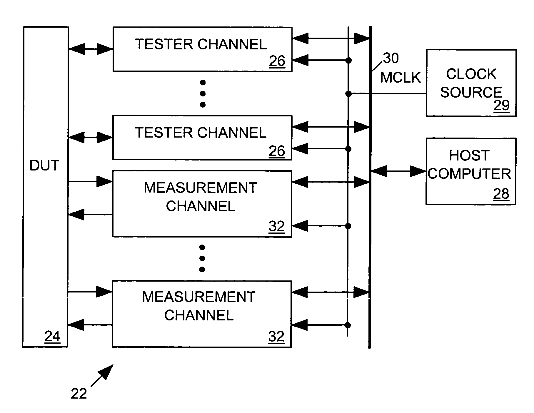
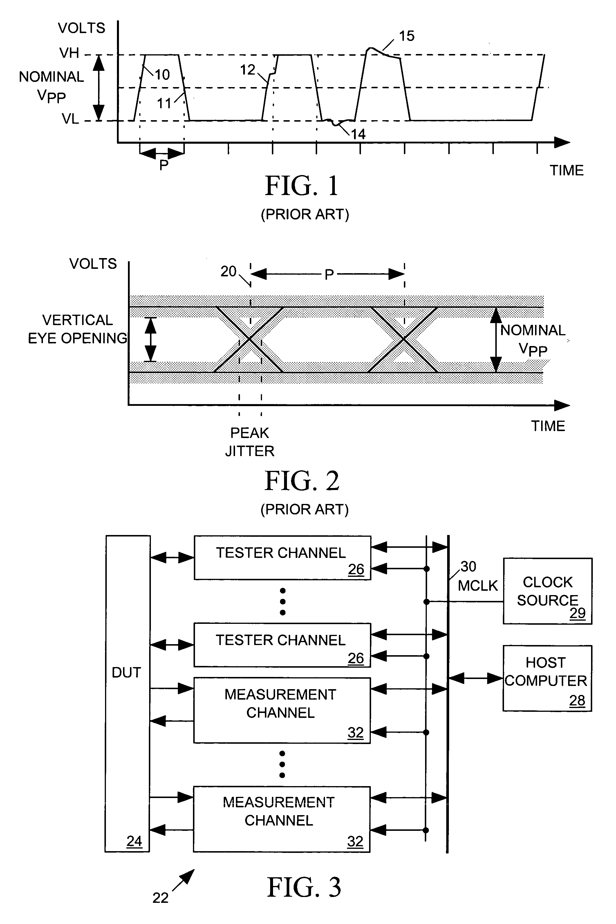
[0034]FIG. 3 depicts an integrated circuit (IC) tester 22 incorporating the present invention. Tester 22 includes a set of conventional tester channels 26, each connected to a separate pin of IC device under test (DUT) 24. Programmed by instructions supplied from a host computer 28 via a bus 30 and synchronized to a master clock signal MCLK produced by a clock source 29, each tester channel 26 may ...


PUM


Abstract

An electronic device under test (DUT) responds to a digital input signal by generating a digital DUT output signal conveying a repetitive digital signal pattern. An apparatus for measuring various characteristics of the DUT output signal includes a trigger generator for generating a series of trigger signal edges in response to selected DUT output signal edges occurring during separate repetitions of the digital signal pattern. The trigger generator can be configured to generate each trigger signal edge in response to the same or a different edge of the digital signal pattern. The apparatus determines when a DUT output signal edge occurs by determining when the DUT output signal rises above or falls below adjustable reference voltages. The apparatus alternatively responds to each trigger signal edge by measuring a period between two different edges of the digital signal pattern and or by repetitively sampling the DUT output signal to determine its state.

Description

BACKGROUND OF THE INVENTION [0001] 1. Field of the Invention [0002] The invention relates in general to automated test equipment, and in particular to a system for measuring characteristics of a digital signal including its jitter, analog noise levels, period, frequency, skew, and rise and fall times. [0003] 2. Description of Related Art [0004] Digital integrated circuits (ICs) communicate through digital data signals, and when a transmitting IC transmits a digital data signal to a receiving IC, the transmitter typically synchronizes state changes in the digital data signal to leading (or trailing) edges of a periodic clock signal so that the state changes within the data signal will occur at predictable times. To produce a data sequence represented by successive states of the digital signal, the receiver need only digitize the data signal with an appropriate sampling phase and frequency. In some communication systems, a transmitter sending a digital data signal to a receiver also s...

Claims


Application Information

Patent Timeline
Patent Type & Authority Applications(United States)
IPC IPC(8): G01R31/28
CPCG01R31/31932G01R31/3191
Inventor ALMY, THOMAS ARTHURFRISCH, ARNOLD M.
Owner CREDENCE SYSTEMS
Why Eureka
Try Eureka