Fusion process for conduit

a technology of fusion process and conduit, which is applied in the direction of dough shaping, manufacturing tools, other domestic objects, etc., can solve the problems of reducing line pressure, unnecessarily allowing water to leak into the area surrounding the piping, and unsightly and intrusive above ground piping, so as to prevent infiltration through these joints, effective use of connection, and high strength characteristics

Active Publication Date: 2006-04-06
UNDERGROUND SOLUTIONS INC
View PDF63 Cites 17 Cited by
  • Summary
  • Abstract
  • Description
  • Claims
  • Application Information

AI Technical Summary

Benefits of technology

[0014] It is, therefore, an object of the present invention to provide a fusion process for PVC conduit that overcomes the deficiencies of the prior art. It is another object of the present invention to provide a fusion process for PVC conduit that allows for the onsite connection of multiple lengths of PVC conduit. It is a still further object of the present invention to provide a fusion process for PVC conduit that results in a joint that equals the strength of the original conduit and does not increase the diameter of the joint area beyond the original conduit diameter. It is a further object of the present invention to provide a fusion process for PVC conduit that provides a single piece of starting stock with no mechanical joints, which precludes infiltration through these joints. It is yet another object of the present invention to provide a fusion process for PVC conduit that produces a joint that is capable of subsequent expansion and use in pressurized conduit system. It is another object of the present invention to provide a fusion process for PVC that produces a joint that is consistent and has high strength characteristics. It is a further object of the present invention to provide a fusion process and apparatus that can be effectively used in connection with fused pipes and joints in sliplining applications, horizontal directional drilling applications, pipe bursting applications and direct-bury applications.

Problems solved by technology

Typically, such conduit or piping systems are located underground, as aboveground piping would be both unsightly and intrusive.
Normally, after many years of use, or for some other reason, the in-ground piping fails and begins to leak, thereby reducing line pressure and unnecessarily allowing water to leak into the area surrounding the piping.
Such leaks not only affect the system, but also increase the processing costs of the supplier, which, in turn, increases the end user costs.
Due to the underground position of the conduit system, repairing a leaking pipe is particularly labor intensive and time consuming.
However, this merely replaces the problem of a cracked outer pipe with a cracked or otherwise leaking inner pipe.
Still further, using such a pipe-in-pipe system drastically reduces the flow through the conduit system and evidences unwanted and varying pressure parameters.
However, this process requires a larger drill to accommodate the mechanical couplings and joints manufactured from PE or HDPE.
Unlike polyethylene pipe, which is generally joined by heat fusion techniques, PVC pipe has normally been limited to applications that can be serviced by bell-and-spigot joints.
This limitation has restricted the use of PVC pipe in sliplining rehabilitation applications.

Method used

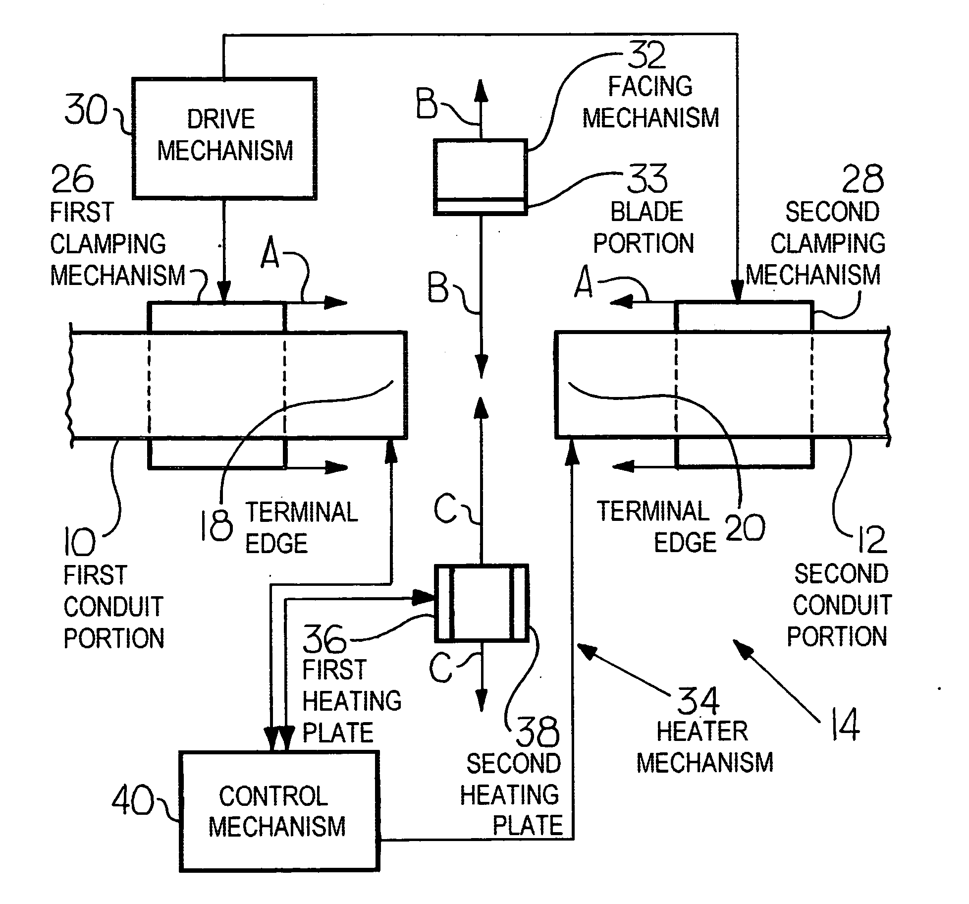
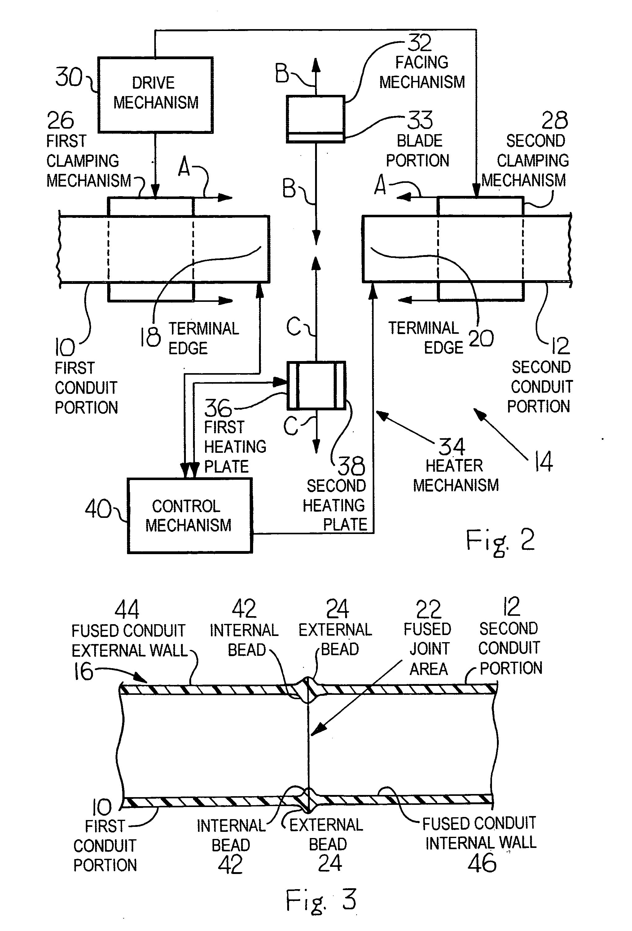

Image

  • Fusion process for conduit
  • Fusion process for conduit
  • Fusion process for conduit

Examples


Embodiment Construction

[0027] For purposes of the description hereinafter, the terms “upper”, “lower”, “right”, “left”, “vertical”, “horizontal”, “top”, “bottom”, “lateral”, “longitudinal” and derivatives thereof shall relate to the invention as it is oriented in the drawing figures. However, it is to be understood that the invention may assume various alternative variations and step sequences, except where expressly specified to the contrary. It is also to be understood that the specific devices and processes illustrated in the attached drawings, and described in the following specification, are simply exemplary embodiments of the invention. Hence, specific dimensions and other physical characteristics related to the embodiments disclosed herein are not to be considered as limiting.

[0028] Various numerical ranges are disclosed in this patent application. Because these ranges are continuous, they include every value between the minimum and maximum values. Unless expressly indicated otherwise, the various...


PUM

PropertyMeasurementUnit
areaaaaaaaaaaa
interfacial pressureaaaaaaaaaa
pressureaaaaaaaaaa

Abstract

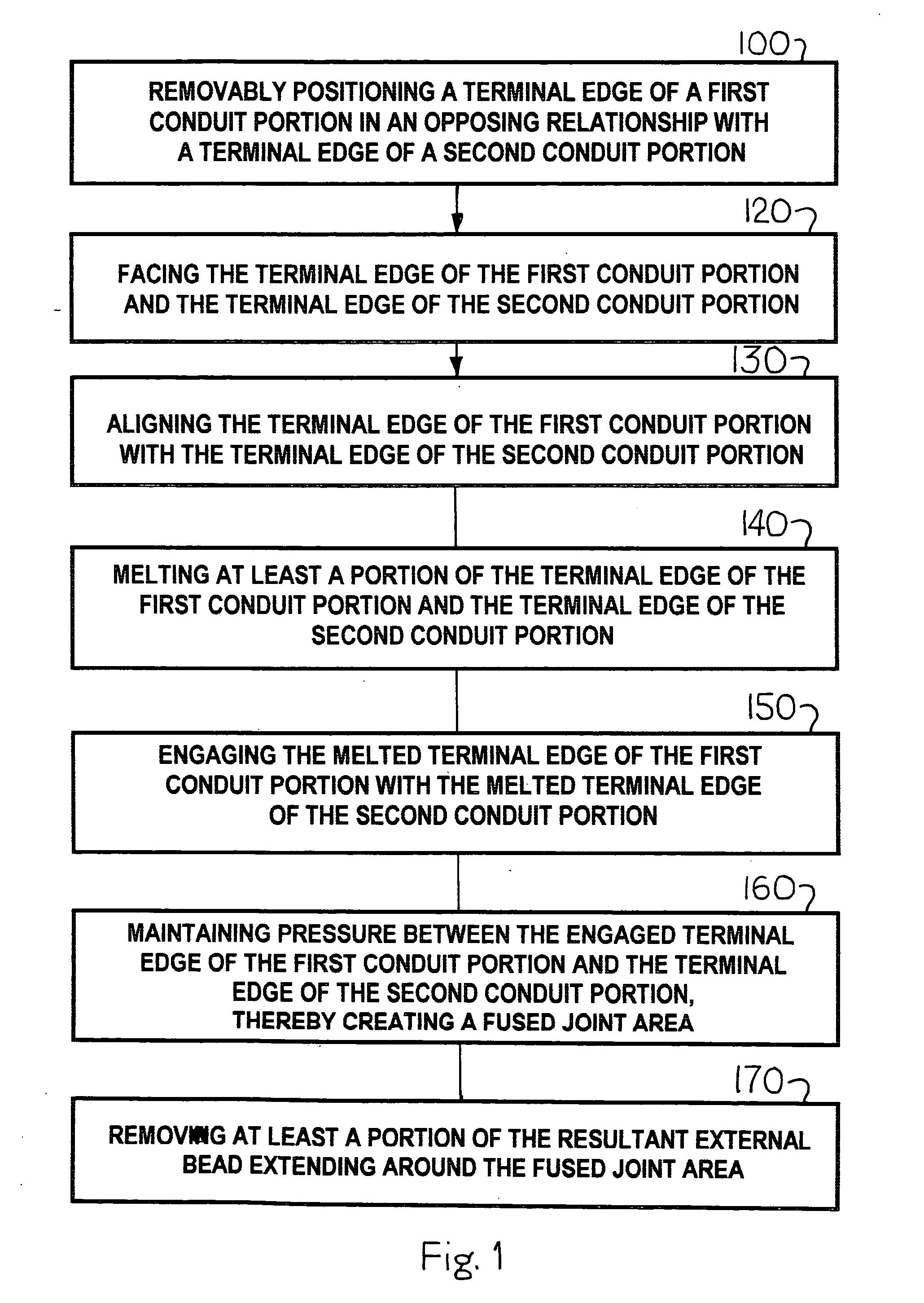
Disclosed is a method and apparatus for use in a fusion process for conduit. The method includes the steps of: removably positioning a first terminal edge of a first conduit portion with a first terminal edge of a second conduit portion; facing the terminal edges of the first conduit portion and the second conduit portion; aligning the terminal edges of the first conduit portion and the second conduit portion; melting at least a portion of the terminal edges of the first conduit portion and the second conduit portion; engaging the melted terminal edge of the first conduit portion with the melted terminal edge of the second conduit portion; maintaining pressure between the engaged terminal edges, thereby creating a fused joint area; and removing at least a portion of the resultant external bead extending around the fused joint area. A fusion apparatus for employing this method is also disclosed.

Description

CROSS REFERENCE TO RELATED APPLICATIONS [0001] This application is a continuation of U.S. patent application Ser. No. 10 / 788,921, filed Feb. 26, 2004, which takes priority from U.S. Provisional Patent Application No. 60 / 478,313, filed Jun. 13, 2003, which are both herein incorporated by reference in their entirety.BACKGROUND OF THE INVENTION [0002] 1. Field of the Invention [0003] The present invention relates generally to systems for fusing or joining conduit or piping sections, such as polyvinyl chloride piping and, in particular, to a fusion process for effectively and permanently joining a first conduit portion to a second conduit portion. [0004] 2. Description of Related Art [0005] Conduit systems are used in many applications throughout the world in order to transfer or convey material, such as water and other fluids, from location to location for distribution throughout the system. For example, extensive conduit systems are used to distribute water to both residences and busi...

Claims


Application Information

Patent Timeline
Patent Type & Authority Applications(United States)
IPC IPC(8): B29C65/00B29C37/04B29C53/20B29C65/20
CPCB29C37/04Y10T156/108B29C65/2015B29C65/2092B29C66/022B29C66/032B29C66/1142B29C66/5221B29C66/71B29C66/80B29C66/91216B29C66/91231B29C66/9241B29C66/929B29C66/967B29C2793/0081B29K2023/06B29K2023/065B29K2027/06B29L2023/22B29C53/20B29C65/7841B29C66/9261B29C66/92211B29C66/961B29C66/91431B29C66/91423B29C65/2061B32B41/00B32B38/0004B32B37/04B29C66/91421B29C65/00B29C66/91921B29C66/02241B29C66/02245Y10T137/0318B29C66/92B29C65/02
Inventor ST. ONGE, BRYANST. ONGE, HENRI
Owner UNDERGROUND SOLUTIONS INC
Why Eureka
Try Eureka