Plastic spring and method and apparatus for making the same

a plastic spring and spring technology, applied in the field of helical springs, can solve the problems of low thermal and electrical conductivity, inconvenient spring steel, and inability to meet the needs of applications, and achieve the effects of maximizing the flat load bearing surface, minimizing side thrust, and avoiding affecting the performance of the spring

Active Publication Date: 2015-01-27
LEE SPRING
View PDF24 Cites 15 Cited by
  • Summary
  • Abstract
  • Description
  • Claims
  • Application Information

AI Technical Summary

Benefits of technology

[0009]Another object of the first aspect of the present invention is to provide a new and improved helical spring made from plastic material having good strength characteristics.
[0024]This design has a plurality of mold sections, each of which has a distinct die surface design that serves as a molding surface for either a top surface or a bottom surface of a particular segment of an active coil of the spring. The die surfaces also serve as interlocking tapered shutoff surfaces relative to the die surfaces of other mold sections to achieve good alignment between the mold sections and to facilitate free release of the molded spring.

Problems solved by technology

However, there are applications for helical springs in which a certain load bearing capability is required, normally provided by spring steel, but for which spring steel is not suitable.
For example, spring steel is not suitable for applications that require that the spring be made from a material having properties such as resistance to chemical corrosion, imperviousness to magnetic fields, retention of properties at elevated temperatures, being lightweight, and low thermal and electrical conductivity, among others.
Such disassembly is expensive to the point that recycling can become cost prohibitive.
However, plastic materials have a relatively low strength as compared to spring steel and traditional spring designs using plastic will generally not provide sufficient load bearing capability or strength to weight ratio for most applications.
Furthermore, while it is desirable to utilize injection molding in the manufacture of plastic products due to its relative economy and high degree of accuracy in forming plastic parts, it is difficult to create practical mold designs for the manufacture of helical springs from plastic material.
However, this conventional method of tool design cannot achieve the smooth helical shape desired for the part.
The main problem is undercuts inherent in a helix which impede the withdrawal of the multi-section mold from the helical spring after the molding operation resulting in kinks every quarter turn at the mating surfaces of the mold sections.
It is also difficult to achieve a uniformly smooth surface for the molded product due to the presence of knit lines from material flows during an injection molding process.

Method used


Image

  • Plastic spring and method and apparatus for making the same
  • Plastic spring and method and apparatus for making the same
  • Plastic spring and method and apparatus for making the same

Examples


Embodiment Construction

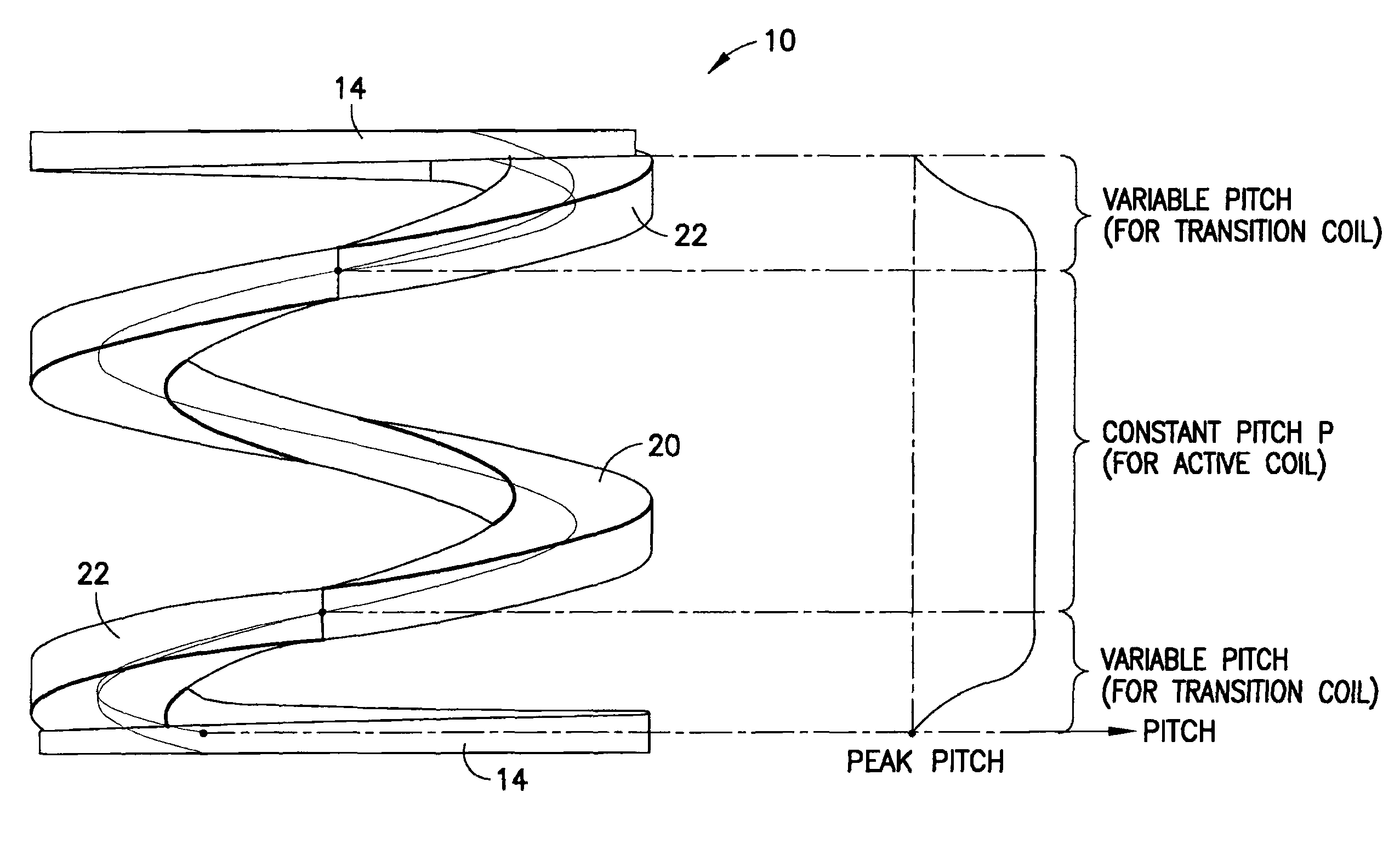
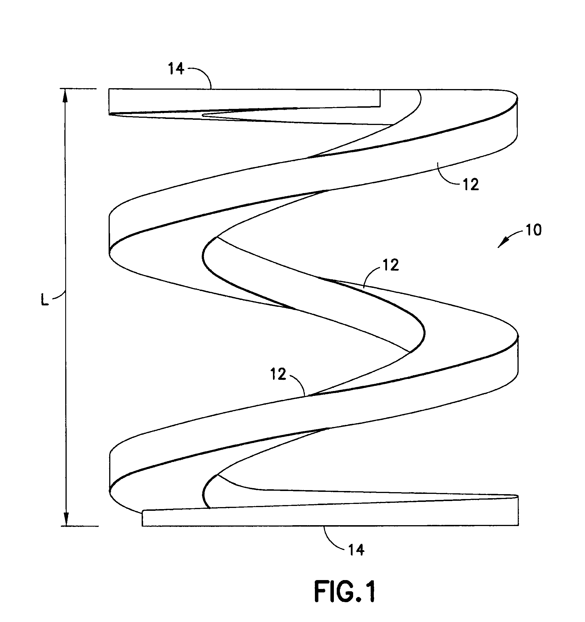
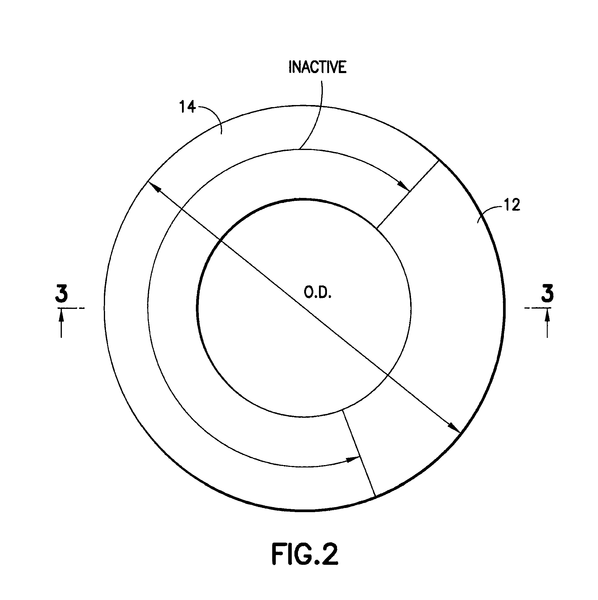
[0045]Referring now to the drawings wherein like reference characters designate identical or corresponding parts throughout the several views, and more particularly to FIGS. 1-3, an embodiment of a spring in accordance with the present invention is designated 10. Spring 10 is formed of plastic material and comprises a helical compression spring having a free length L and an outer diameter O.D., a number of active coils 12 (i.e., coils or segments that contribute to the resistance to a compressive force being applied to the spring) and a pair of inactive end coils 14 (i.e., coils or segments that do not contribute to the resistive force of the spring). The pitch of spring 10 (the distance, center to center, between two coils) is designated P (FIG. 5). For example, the free length L of a spring in accordance with the invention may be approximately ¾ inch while the outer diameter OD of a spring in accordance with the invention may be approximately ½ inch. The number of total coils may ...


PUM

PropertyMeasurementUnit
pitch angleaaaaaaaaaa
strengthaaaaaaaaaa
thermoplasticaaaaaaaaaa

Abstract

This invention provides a helical spring formed of plastic material, comprising a pair of end coils situated at respective ends of said helical spring; at least one full pitch active coil between said pair of end coils; a pair of transition coils, each transition coil interconnecting an end of a respective end coil to an end of a respective proximate full pitch active coil, and having a varying pitch.

Description

FIELD OF THE INVENTION[0001]This invention relates generally to helical springs and, more particularly, to helical springs made from plastic and methods and apparatus for making helical plastic springs.BACKGROUND OF THE INVENTION[0002]Helical springs are used in a wide variety of applications in part due to their simple configuration. Generally, helical springs have an outer diameter sized to fit within a cylindrical bore and / or an inside diameter sized to fit over a rod. Often, the end coils of the spring are ground or otherwise tapered to be in a plane perpendicular or square to the cylindrical axis of the spring so that the reaction of the spring to forces parallel to the cylindrical axis which are applied to the spring includes a minimal amount of radial (side) thrust. Tapering of the ends also reduces the solid height of the spring, i.e., the overall length of the spring in the fully compressed state, so that the spring requires a minimal amount of space in the device of which ...

Claims


Application Information

Patent Timeline
Patent Type & Authority Patents(United States)
IPC IPC(8): F16F1/04B29C45/44B29L31/00F16F1/02
CPCB29C45/44F16F1/021F16F1/042F16F1/047B29L2031/7742
Inventor KEMPF, STEPHENMANGELS, ALBERTNAGLAPURA, SUBRAMANYADIAMOND, SEANMOULDER, BRIANSTRAITON, BRIAN
Owner LEE SPRING
Why Eureka
Try Eureka