High intensity discharge lamp control

US20060071610A1Inactive Publication Date: 2006-04-06THE ACTIVE REACTOR

Image

  • High intensity discharge lamp control
  • High intensity discharge lamp control
  • High intensity discharge lamp control

Examples


Embodiment Construction

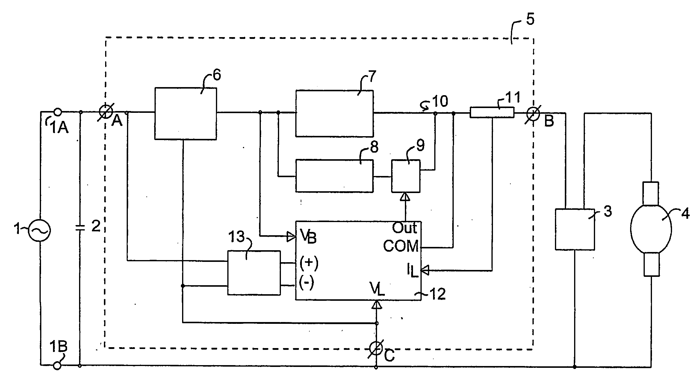
[0077] Referring to FIG. 1, this shows a schematic block diagram of the arrangement of components of a lighting system configured according to one embodiment of the present invention.

[0078] The circuit includes an a.c. power source 1, having terminals 1A and 1B, connected to a lamp controller 5 which is placed in circuit with an ignitor 3 and an HID lamp 4. The ignitor 3 may be any conventional ignitor that is suitable for the initial starting of an HID lamp, preferably the ignitor 3 is an electronic ignitor. The lamp 4 may be any suitable HID lamp. Although any suitable HID lamp may be controlled by the present invention, the invention is particularly suitable for controlling high pressure sodium, metal halide or mercury vapour discharge lamps, and for controlling lamps with a power rating between about 150 watts and about 2000 watts, e.g. lamps rated at greater than or equal to about 250 watts, 400 watts, or 1000 watts. The circuit also includes a power factor correction capacito...


PUM


Abstract

A controller 5 for a high intensity discharge lamp 4 includes a primary ballast for providing a primary current to the lamp 4, and a current injector which in the case shown comprises a control ballast 8 and a switch 9 (e.g. a triac) controlled by a control unit 12. The current injector injects a secondary current into the lamp 4 that is less than the primary current and can be varied by the control unit 12, e.g. by varying the amount of time within an a.c. cycle that the control ballast 8 is switched into the circuit. The controller 5 allows the lamp 4 to be controlled, for example, to operate at a constant power (variable light output) or at a constant light output (variable power).

Description

RELATED APPLICATIONS [0001] This invention is related to and claims priority from Australian Patent Application No. 2003902210, filed May 8, 2003, entitled High Intensity Discharge Lamp Control; and PCT Application No. PCT / AU2004 / 000601, filed May 7, 2004, entitled High Intensity Discharge Lamp Control, which are incorporated herein by reference.FIELD OF THE INVENTION [0002] The present invention broadly relates to controllers and circuits for controlling the operation of high intensity discharge lamps. It also broadly relates to methods of controlling the operation of high intensity discharge lamps. BACKGROUND [0003] High intensity discharge (HID) lamps include high pressure sodium lamps, metal halide lamps and mercury vapour lamps. They are distinct from for example fluorescent lamps. For example, they tend to operate under higher pressures and temperatures, they emit visible light directly (although they may also include some phosphor coatings), and they are generally compact lig...

Claims


Application Information

Patent Timeline
06 Apr 2006
Publication
US20060071610A1
IPC
H05B37/02; H05B41/288; H05B41/36; H05B41/392
CPC
H05B41/2885; H05B41/3921; Y02B20/202; Y10S315/07; Y02B20/00
Inventors
DLUZNIAK, RICHARD