Current sensor

a current sensor and current sensor technology, applied in the direction of magnetic measurement, dynamo-electric motor meters, instruments, etc., can solve the problem of difficult adjustment of the balance of the four magnetoresistive elements, and achieve the effect of easy adjustment of the offset value at a zero magnetic field, high sensitivity and high precision

Inactive Publication Date: 2006-04-06
TDK CORPARATION
View PDF22 Cites 102 Cited by
  • Summary
  • Abstract
  • Description
  • Claims
  • Application Information

AI Technical Summary

Benefits of technology

[0008] The present invention has been achieved in consideration of such problems and an object of the invention is to provide a current sensor capable of adjusting an

Problems solved by technology

In many cases, it becomes therefore difficult to adju

Method used


Image

  • Current sensor
  • Current sensor
  • Current sensor

Examples


Embodiment Construction

[0024] An embodiment of the invention will be described in detail hereinbelow with reference to the drawings.

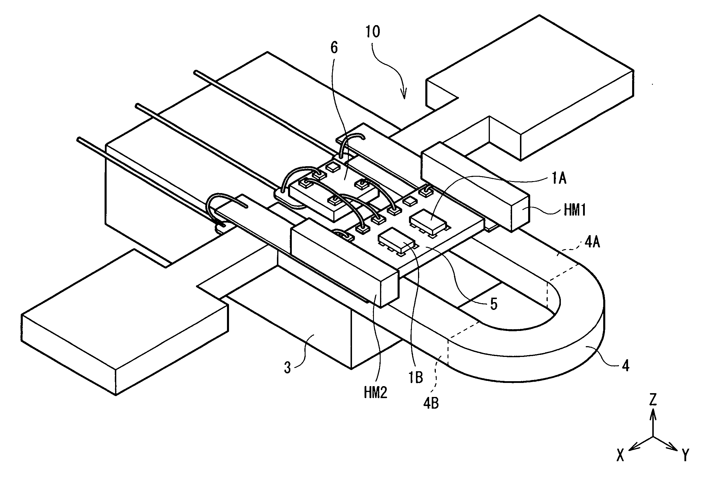
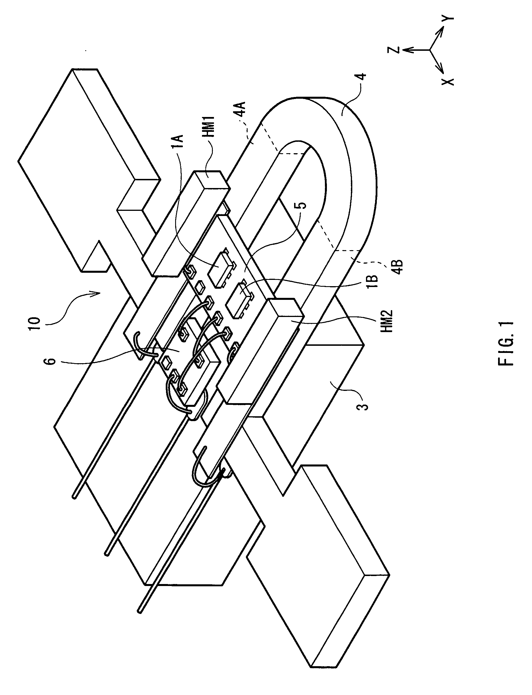
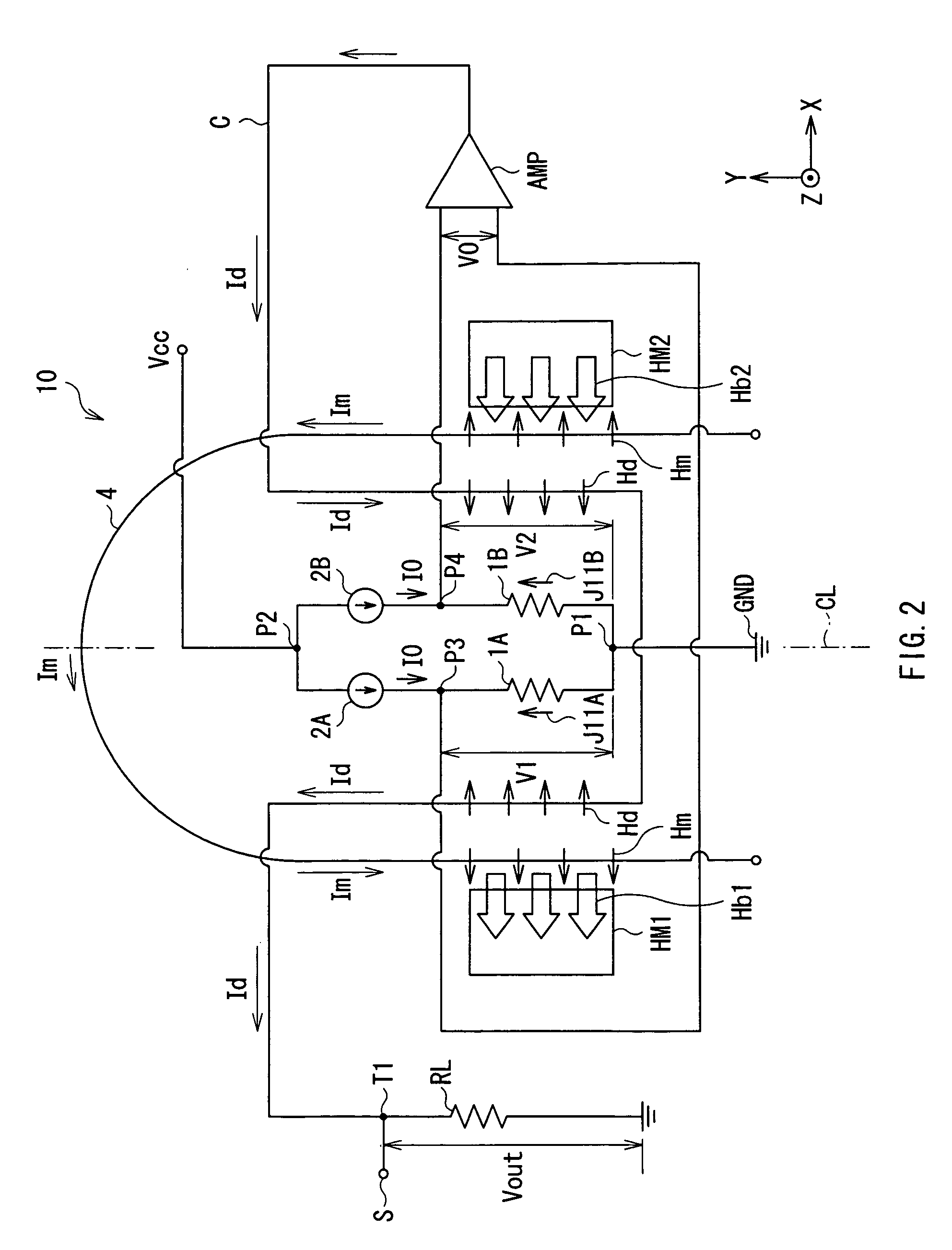
[0025] First, the configuration of a current sensor as an embodiment of the invention will be described with reference to FIGS. 1 and 2. FIG. 1 is a schematic view illustrating a perspective configuration of a current sensor 10 according to the embodiment. FIG. 2 shows a circuit configuration of the current sensor 10 illustrated in FIG. 1. All of arrows of a current Im to be detected, a compensating current Id, a current magnetic field Hm, a compensating current magnetic field Hd, bias magnetic fields Hb1 and Hb2, and a current I0 (all described later) show directions relative to first and second magnetoresistive elements.

[0026] The current sensor 10 is an ammeter for measuring the current Im to be detected supplied to a conductor 4 formed on a substrate 3, and has the first and second magnetoresistive elements 1A and 1B connected to each other at a first connection point P...


PUM


Abstract

The present invention provides a current sensor capable of adjusting an offset value at a zero magnetic field more easily and detecting a current magnetic field generated by a current to be detected with high sensitivity and high precision. The current sensor has: first and second magnetoresistive elements disposed along a conductor so that resistance values change in directions opposite to each other in accordance with a current magnetic field generated by a current to be detected flowing in the conductor; and first and second constant current sources that supply constant currents equal to each other to the first and second magnetoresistive elements, respectively. The current sensor further includes a differential amplifier that detects the difference between voltage drops occurring in the first and second magnetoresistive elements by the constant current. The current to be detected is detected on the basis of the difference between the voltage drops.

Description

BACKGROUND OF THE INVENTION [0001] 1. Field of the Invention [0002] The present invention relates to a small-sized current sensor capable of sensing a change in current flowing in a conductor with high sensitivity. [0003] 2. Description of the Related Art [0004] One of general methods of measuring control current for controlling control equipment or the like is a method of indirectly measuring control current by detecting the gradient of a current magnetic field generated by the control current. A concrete example is a method of forming a Wheatstone bridge by using four magnetoresistive elements such as giant magnetoresistive elements (hereinbelow, GMR elements) producing giant magnetoresistive effect, disposing the Wheatstone bridge in the current magnetic field, and detecting the gradient of the current magnetic field (refer to, for example, U.S. Pat. No. 5,621,377). [0005] By forming the Wheatstone bridge as described above, noise (interfering magnetic field) from the outside and...

Claims


Application Information

Patent Timeline
IPC IPC(8): G01R33/07
CPCG01R15/205G01R33/09
Inventor SHOJI, SHIGERU
Owner TDK CORPARATION
Why Eureka
Try Eureka