Electronically enabling devices remotely

a technology of electromagnetic enablement and remote control, applied in the direction of computer control, program control, securing communication, etc., can solve problems such as the inability to operate devices

Inactive Publication Date: 2006-04-06
LAMAR DAVID
View PDF9 Cites 41 Cited by
  • Summary
  • Abstract
  • Description
  • Claims
  • Application Information

AI Technical Summary

Benefits of technology

[0025] With the development and standardization of ad hoc wireless networking now taking place, the device could optionally have the means of communication with such a network. These new network topologies, such as Star or Mesh and combinations thereof, have no central orchestrating

Problems solved by technology

After the expiration of the time period, the device could not be

Method used


Image

  • Electronically enabling devices remotely
  • Electronically enabling devices remotely
  • Electronically enabling devices remotely

Examples


Embodiment Construction

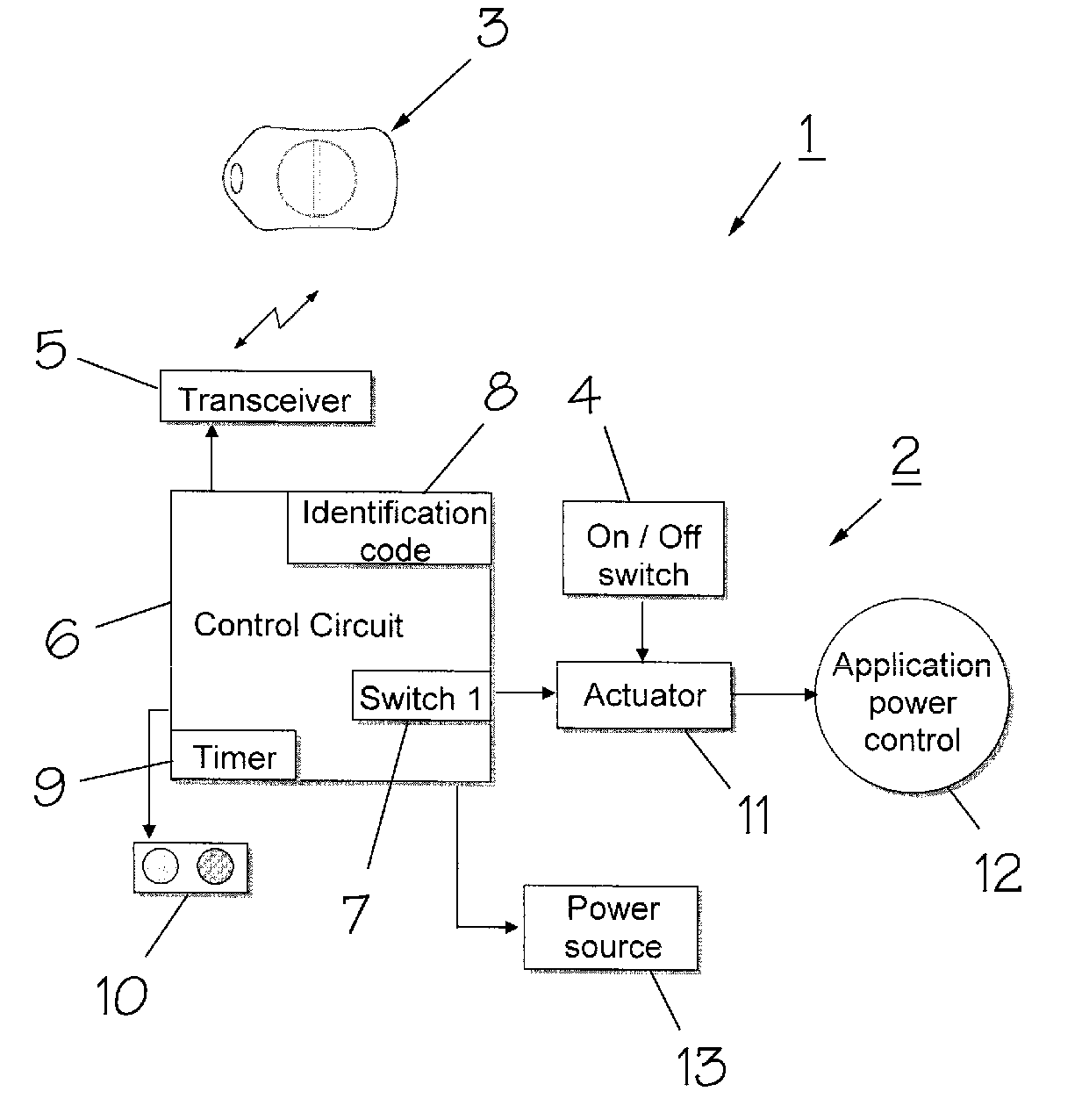
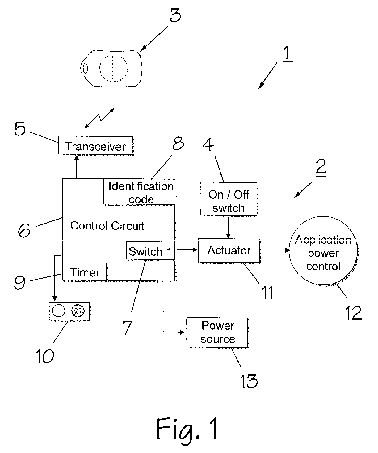
[0031] Referring to FIG. 1, a device 1 according to this invention comprises tool 2 and remote wireless electronic key 3 that can communicate with tool 2. Tool 2 may be a power tool, such as a drill or saw, a lawn mower, a digital camera, computer, digital music players, video cameras, digital projectors or video game player. It may be stationary or portable. When tool 2 is activated it can turn on an electric motor, gasoline engine, diesel engine, compressed air tool, chemical tool (e.g., a tool operated by firing blank ammunition), close an electric circuit, or another operation. Tool 2 has an on / off switch 4 that enables the operator of the tool to turn the tool on and off as it is needed. On / off switch 4 will typically close an electric circuit, but may also turn the tool on and off by other means. Tool 2 is further provided with a transceiver 5 that can send and receive coded wireless signals to and from electronic key 3. A control circuit 6 within tool 2 compares a coded elect...


PUM


Abstract

A device has (1) an electronic key that transmits a wireless coded signal and (2) at least one tool that can receive that signal. The coded signal is compared to a coded signal stored in said tool. If the coded signal matches the stored signal, a switch is closed for a predetermined amount of time. An on/off switch then enables the user of the tool to turn the tool on and off during the predetermined amount of time. After the predetermined amount of time, the switch is opened so that the tool can no longer be used. Opening the switch may be delayed if the tool is in use. The tool may also contain a unique identification code that can be read by various electronic means to identify the tool.

Description

CROSS-REFERENCE TO RELATED APPLICATION [0001] This application claims priority from U.S. Provisional Application No. 60 / 612,399, filed Sep. 24, 2004.BACKGROUND OF THE INVENTION [0002] This invention relates to a device that is remotely enabled and disabled. In particular, it relates to a device that is unlocked remotely by means of an electronic key for a predetermined period of time, after which the device is automatically disabled. [0003] Easily carried, but expensive devices, such as digital cameras, video cameras, laptop computers, electronic instruments, and power tools, are very tempting to thieves. Currently, there is no effective, easy-to-use method of protecting such devices from theft. For example, while cell phones have a built-in electronic combination lock that prevents calls when activated, virtually no one uses it because it because the procedure for activating and deactivating it is cumbersome and time-consuming. [0004] In addition to thieves, devices may also be vul...

Claims


Application Information

Patent Timeline
IPC IPC(8): G05B19/00H04Q5/22
CPCB25F5/00G07C9/00309G07C2209/08
Inventor LAMAR, DAVID
Owner LAMAR DAVID
Why Eureka
Try Eureka