
Cage telemetry system using intermediate transponders

a telemetry system and transponder technology, applied in signaling systems, instruments, animal husbandry, etc., can solve the problems of large wiring burden of such sensors, inability to easily fit in a cage, and large wiring requirements of typical temperature sensor devices and the like, so as to reduce the transmission power and/or antenna requirements, the effect of reducing the siz

Inactive Publication Date: 2006-04-06
SIEMENS AG +1
View PDF19 Cites 30 Cited by
  • Summary
  • Abstract
  • Description
  • Claims
  • Application Information

AI Technical Summary

Benefits of technology

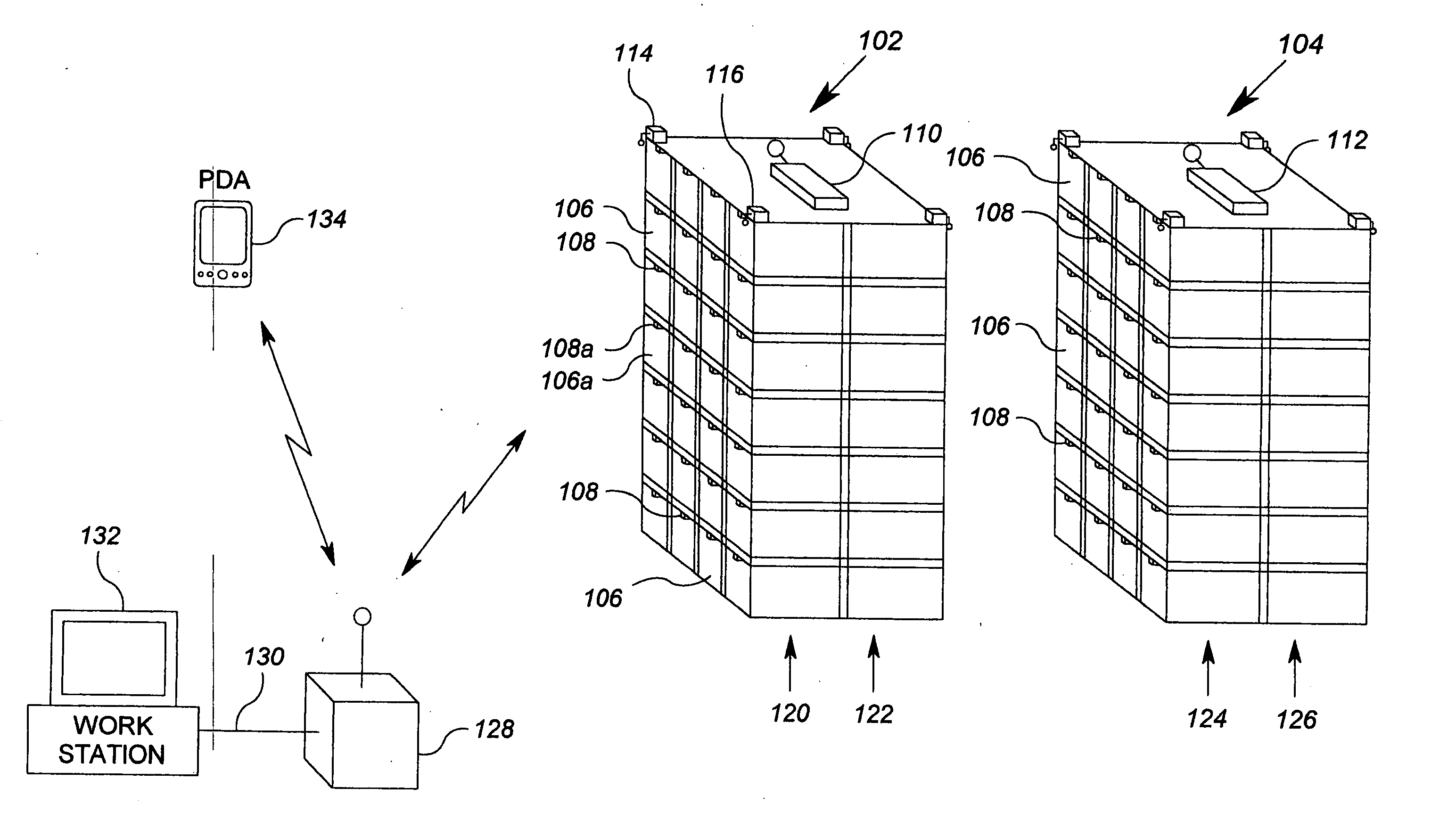
[0006] The present invention addresses the above described need, as well as others, by providing a remote sensor assembly that employs telemetry modules in cages and radio transponders corresponding to different groups of cages, each radio transponder operable to communicate with a hub. The radio transponders communicate with the telemetry modules in their corresponding cage group, and relay information to the hub. The result of combining such elements is that number of cages may have telemetry devices that communicate to a single hub in a space or room, without requiring signal wiring between the hub and each telemetry device. The use of the cage group transponders reduces the transmission power and / or antenna requirements for the telemetry devices, thereby also reducing size.
[0008] In preferred embodiment, the first and second radio transponders use wireless communications to communicate with the hub element, even further reducing wiring requirements. In one implementation, each cage group is a rack of cages.

Problems solved by technology

However, typical temperature sensor devices and the like are too large to fit conveniently within an animal cage, particularly when several sensor devices are used to monitor various conditions.
A further impediment to the use of generally available sensor devices in a cage environment is the significant wiring burden associated with such sensors.
If multiple sensors are used in an array of cages, the wiring requirements can be staggering.

Method used


Image

  • Cage telemetry system using intermediate transponders
  • Cage telemetry system using intermediate transponders
  • Cage telemetry system using intermediate transponders

Examples


Embodiment Construction

[0022]FIG. 1 shows a representative block diagram of an exemplary cage data system 100 according to various inventive aspects described herein. The cage data system 100 includes a plurality of racks 102, 104, each having a plurality of cages 106. The cages 106 are arranged in rows and columns in the racks 102 and 104. While the precise dimensions of the cages 106 are not important to disclosure of the invention, each cage 106 is an enclosure preferably having a rectangular footprint that has a size typical in the industry for the animal it is meant to contain. Each cage 106, as is known in the art, includes openings at least at the ends thereof to allow for ventilation. In accordance with this embodiment of the invention, each cage 106 also includes a wireless module 108 that is capable of providing telemetry information in conjunction with other elements of the system 100.

[0023] The cage data system 100 also includes a rack data transponder 110 associated with the first rack 102 a...


PUM


Abstract

A cage telemetry system includes a plurality of cage groups, first and second radio transponders, and a hub element. The plurality of cage groups are located within a space. Each cage group includes a plurality of animal cages, each cage associated with at least one telemetry module. The first radio transponder is operable to effect wireless communications with each telemetry module of a first cage group. The second radio transponder is operable to effect wireless communications with each telemetry module of a second cage group. The hub element is operable to communicate with the first radio transponder and the second radio transponder, and is further operably connected to a computer network.

Description

CROSS REFERENCE TO RELATED APPLICATIONS [0001] Cross-reference is made to co-pending U.S. patent application Ser. No. ______ [Express Mail No. EV505541465US, attorney docket 1867-0071], entitled “Two Dimensional RF Location Method and Apparatus”, filed Sep. 27, 2004, and to co-pending U.S. patent application Ser. No. ______ [Express Mail No. EV505541457US, attorney docket 1867-0059], entitled “Cage Telemetry Module and System”, filed Sep. 27, 2004.FIELD OF THE INVENTION [0002] The present invention relates generally to cage telemetry systems, and more particularly, systems for remotely obtaining sensor and / or location information for one or more cages. BACKGROUND OF THE INVENTION [0003] Environmental sensor and telemetry systems are used to monitor conditions in a variety of implementations. Temperature, humidity and light sensors are often employed in building control systems to assist in regulating a comfortable environment and / or increasing efficiency in power consumption. Smoke ...

Claims


Application Information

Patent Timeline
IPC IPC(8): G08B1/08
CPCA01K1/031A01K11/006
Inventor AHMED, OSMANGLANZER, MARTINFLEISCHER, MAXIMILIANGULDEN, PETER
Owner SIEMENS AG
Learn More