Image processing apparatus, and computer program

a technology of image processing apparatus and computer program, which is applied in the direction of 3d-image rendering, instruments, computing, etc., can solve the problems of long time required to generate a display image and switch the display image, difficult to smoothly change the display image, and calculation time, etc., to achieve the effect of faster speed

Inactive Publication Date: 2006-04-06
KONICA MINOLTA MEDICAL & GRAPHICS INC
View PDF3 Cites 16 Cited by
  • Summary
  • Abstract
  • Description
  • Claims
  • Application Information

AI Technical Summary

Benefits of technology

[0013] It is therefore an object of the present invention to provide a technique capable of generating a depth map in volume rendering at higher speed.

Problems solved by technology

The volume rendering using the depth map requires, however, some calculation time for regenerating a depth map each time the direction of sight line is changed.
Consequently, it takes a long time to generate a display image and to switch the display image, and it is difficult to smoothly change a display image in accordance with the change of the projection plane, that is, the direction of sight line.

Method used


Image

  • Image processing apparatus, and computer program
  • Image processing apparatus, and computer program
  • Image processing apparatus, and computer program

Examples


Embodiment Construction

[0025] A preferred embodiment of the present invention will be described below with reference to the drawings.

Outline of Image Processing System

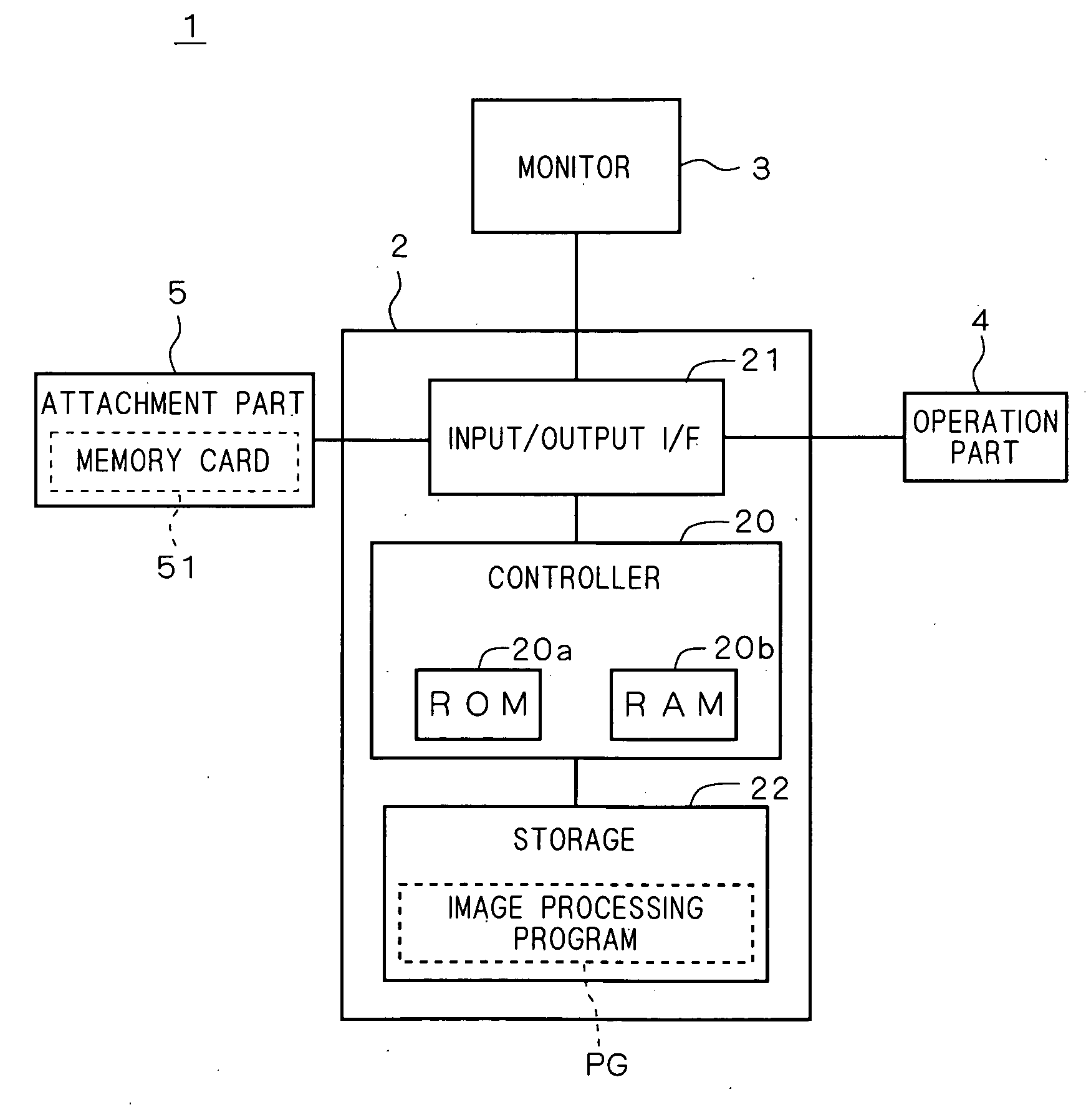
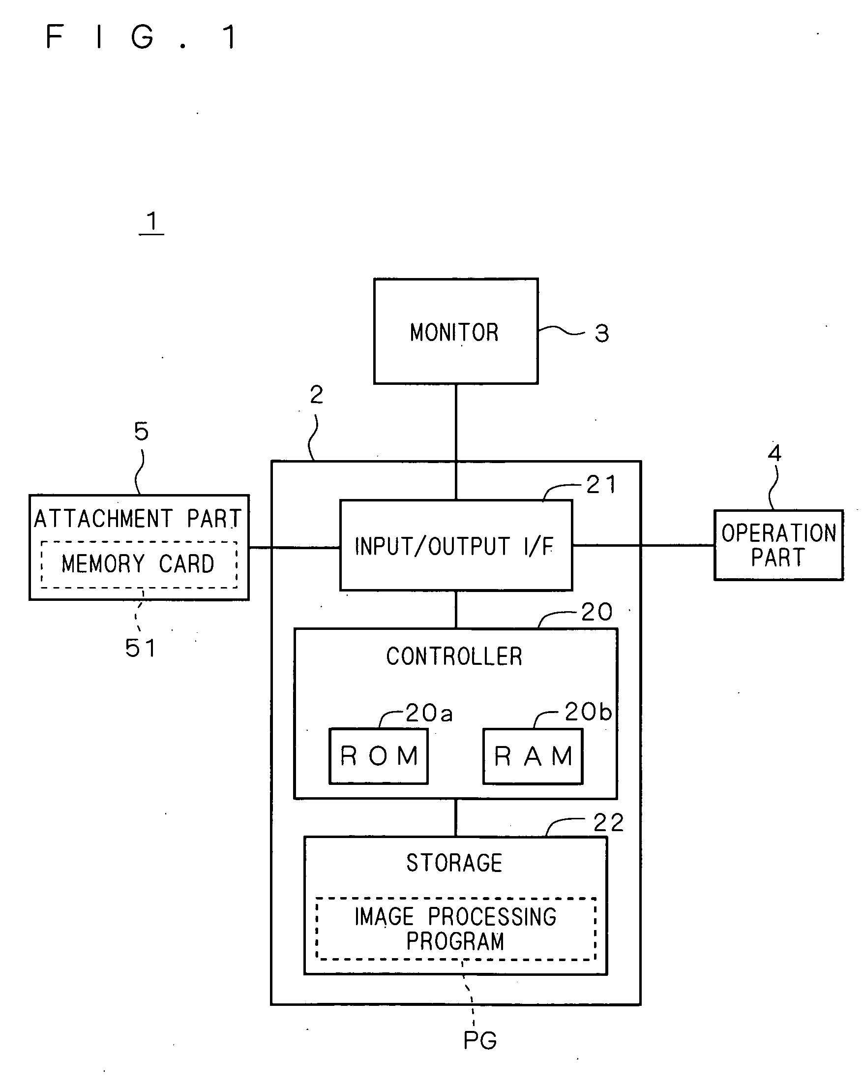
[0026]FIG. 1 illustrates an outline of an image processing system 1 according to a preferred embodiment of the present invention.

[0027] The image processing system 1 has a personal computer 2 (hereinafter, simply referred to as “PC”), a monitor 3 and an attachment part 5 connected to the PC 2 so as to be able to transmit / receive data to / from the PC 2, and an operation part 4 used by a user to enter various selection matters and the like to the PC 2.

[0028] The PC 2 includes a controller 20, an input / output I / F 21, and a storage 22.

[0029] The input / output I / F 21 is an interface (I / F) for transmitting / receiving data to / from the monitor 3, the operation part 4 and the attachment part 5, and transmits / receives data to / from the controller 20.

[0030] The storage 22 takes a form of, for example, a hard disk which stores an image processing pro...


PUM


Abstract

When volume data of a three-dimensional object to be processed is read and stored into a predetermined storage, first, a plurality of reference planes are set and a plurality of reference distance maps each indicative of distribution of distances between the three-dimensional object and each of the reference planes are generated. Next, when an actual projection plane onto which the three-dimensional object is projected in the volume rendering is set, two or more distance maps out of the plurality of reference distance maps are converted into two or more converted distance maps in accordance with a positional relation between two or more reference planes corresponding to the two or more distance maps and the actual projection plane, and integrating the resultants, thereby generating a distance map for visualization indicative of distribution of distances between the three-dimensional object and the actual projection plane.

Description

[0001] This application is based on application No. 2004-292410 filed in Japan, the contents of which are hereby incorporated by reference. BACKGROUND OF THE INVENTION [0002] 1. Field of the Invention [0003] The present invention relates to a technique of generating a display image by volume rendering. [0004] 2. Description of the Background Art [0005] As a method of visualizing and displaying data indicative of a three-dimensional structure, a method called volume rendering is known. The volume rendering includes a method called ray casting. [0006] The volume rendering is often used at the time of displaying a three-dimensional image, for example, as a medical-use image for a diagnosis in the medical field. For example, at the time of observing an affected area or the like while appropriately changing the direction of sight line, it is desired to switch a display image quickly so as not to apply stress on a user. [0007] Various methods of increasing the speed of volume rendering ha...

Claims


Application Information

Patent Timeline
Patent Type & Authority Applications(United States)
IPC IPC(8): G06T15/00G06T15/08
CPCG06T15/08
Inventor FUJIWARA, KOICHITOYAMA, OSAMU
Owner KONICA MINOLTA MEDICAL & GRAPHICS INC
Why Eureka
Try Eureka