Surface plasmon resonance sensor

a surface plasmon and sensor technology, applied in the field of surface plasmon resonance (spr) sensors, can solve the problems of reducing the possibility of contamination of fluids pumped through the flow cell, and reducing the cost of production

Inactive Publication Date: 2006-04-06
BIO RAD LAB INC
View PDF22 Cites 31 Cited by
  • Summary
  • Abstract
  • Description
  • Claims
  • Application Information

AI Technical Summary

Benefits of technology

[0030] It is noted that a “valveless” flow cell produced in accordance with an embodiment of the present invention is expected to be generally less expensive to produce than prior art flow cells comprising valves to control liquid flow. As a result, a flow cell made in accordance with an embodiment of the present invention may be sufficiently inexpensive to be disposable after being used once. By using a “disposable” flow cell once, possibility of contamination of fluids that are pumped through the flow cell may be reduced.
[0031] An aspect of some embodiments of the present invention relates to providing an illumination system for SPR sensors for illuminating a same relatively large region of a sensor surface with

Problems solved by technology

Many conventional SPR methods and apparatus for forming probe layers, flowing liquids over probe layer sur

Method used


Image

  • Surface plasmon resonance sensor
  • Surface plasmon resonance sensor
  • Surface plasmon resonance sensor

Examples


Embodiment Construction

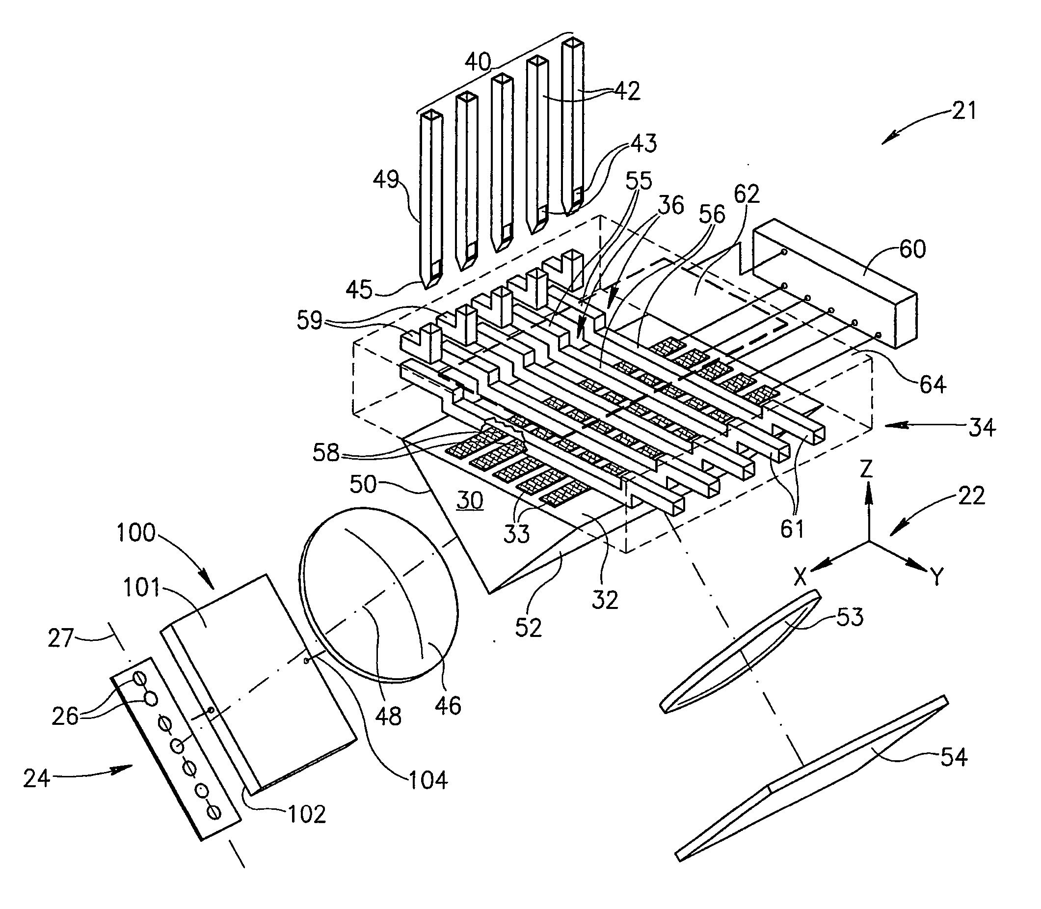
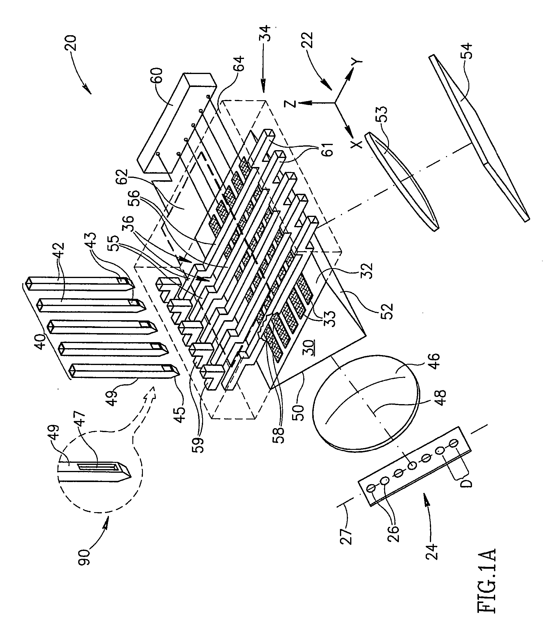
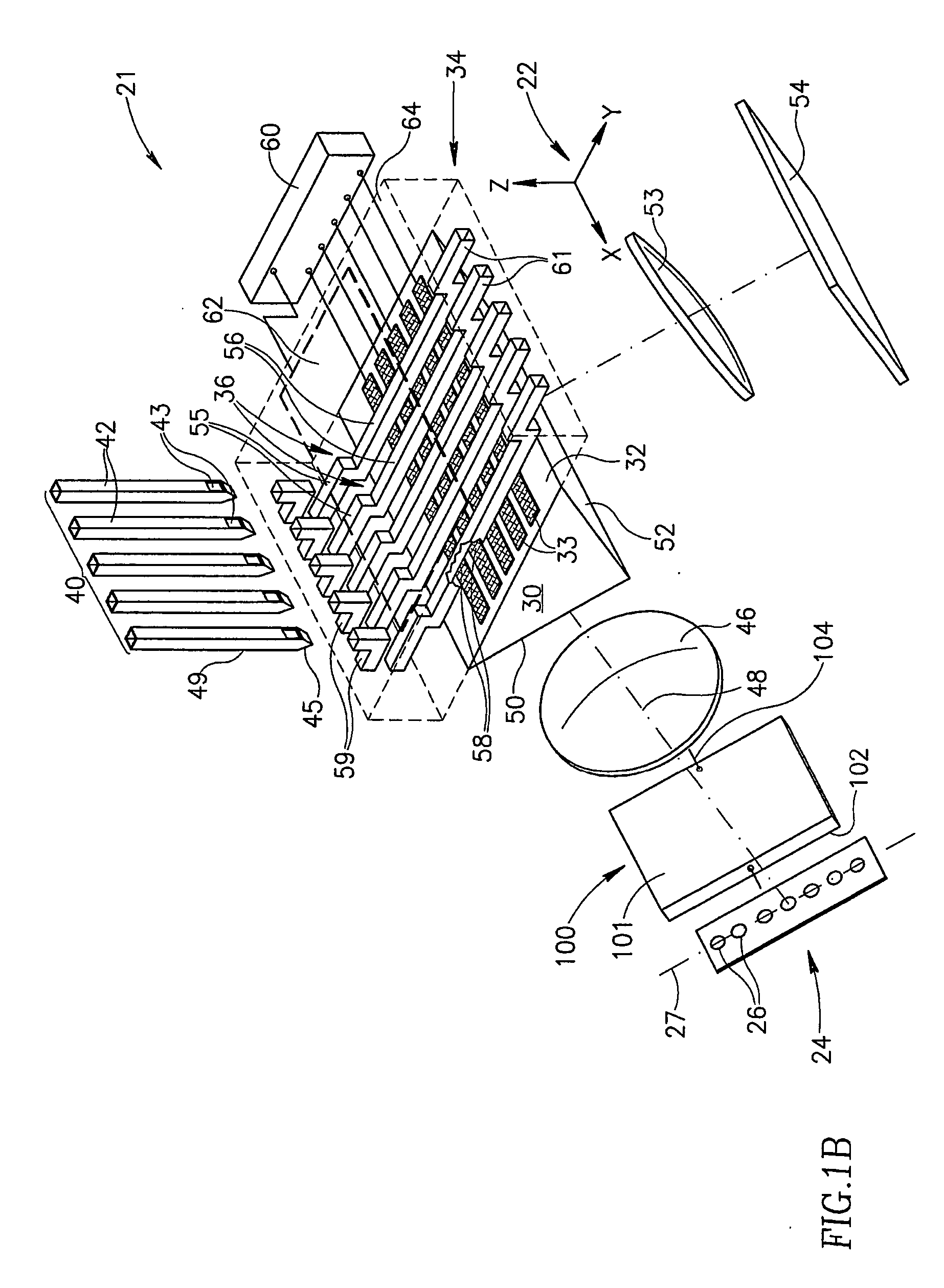
[0074]FIG. 1A schematically shows an SPR sensor 20 in accordance with an embodiment of the present invention. For convenience of discussion location and position of elements and features of SPR sensor 20 are referred to a coordinate system 22.

[0075] SPR sensor 20 comprises an optionally linear array 24 of light sources 26 having an array axis 27 and a prism 30 having a sensor surface 32. A flow cell 34 comprises microchannels 36 for flowing liquid across and in contact with sensor surface 32 and a probe layer (not shown) of desired ligands generated on a suitable SPR conductor formed on the sensor surface. In SPR sensor 20 the probe layer is generated on an SPR conductor optionally comprising a plurality of strip electrodes 33.

[0076] An array 40 of flow needles 42 coupled to suitable pumping apparatus (not shown) is optionally used to introduce liquids into microchannels 36. Operation of flow needles 42 in introducing liquid into microchannels 36 is described below. Microchannels ...


PUM


Abstract

An SPR sensor comprising: a thin conducting layer comprising at least one conductive element formed on a surface of a transparent substrate; an illumination system controllable to illuminate an interface between the conducting layer and the substrate; a photosensitive surface that generates signals responsive to light from the light source that is reflected from a region of the interface; a flow cell formed with at least one flow channel having a lumen defined by a wall at least a portion of which is formed from an elastic material and a portion of which is formed by a region of the conducting layer; and at least one hollow needle having an exit orifice communicating with the needle's lumen and wherein fluid flow is enabled between the flow channel and the needle's lumen by puncturing the elastic material with the at least one needle so that the exit orifice communicates with the flow channel lumen.

Description

FIELD OF THE INVENTION [0001] The invention relates to surface plasmon resonance (SPR) sensors and in particular to methods and apparatus for forming a probe layer on an SPR sensor surface, illuminating an SPR sensor surface and controlling liquid flow in an SPR sensor. BACKGROUND OF THE INVENTION [0002] SPR sensors generate optical signals responsive to the dielectric constant and / or thickness, hereinafter referred to collectively as “optical properties”, of regions of a layer, hereinafter referred to as a “probe layer”, of material contiguous with a thin layer of conducting material. The thin conductive layer, hereinafter an “SPR conductor”, typically has a thickness less than about 100 nm and is generally formed from a metal, usually silver or gold, on a surface of a transparent substrate such as glass. The surface on which the SPR conductor is formed is hereinafter referred to as a “sensor surface”. [0003] Optionally, such as in a Kretschmann configuration of an SPR sensor, the ...

Claims


Application Information

Patent Timeline
IPC IPC(8): G01N21/55G01N21/05
CPCG01N21/553G01N2021/058G01N21/55
Inventor RAN, BOAZNOTCOVICH, ARIELGLIPSON, ARIELNIMRI, SHAYLIPSON, STEPHANGLIPSON, DORON
Owner BIO RAD LAB INC
Why Eureka
Try Eureka