Confocal microscope

a microscope and confocal technology, applied in the field ofconfocal microscopes, can solve the problems of inability to achieve confocal effect, inability to function optical filtering in longitudinal direction of slit,

Inactive Publication Date: 2006-04-06
YOKOGAWA ELECTRIC CORP
View PDF7 Cites 41 Cited by
  • Summary
  • Abstract
  • Description
  • Claims
  • Application Information

AI Technical Summary

Benefits of technology

[0016] An object of the invention is to provide a confocal microscope which enables to achieve a confocal effect with regard to all of directions at inside of an observed image face by using a multipinhole array as an optical filtering element for achieving the confocal effect.
[0029] According to the confocal microscope, the following advantages are achieved.
[0030] Since the confocal microscope has the first multipinhole array which functions the plurality of point light sources and the second multipinhole array as optical filtering elements, the confocal microscope can achieve the confocal effect with regard to all of directions within the observed image face.
[0031] Since the confocal microscope has the microlenses for converging the laser light at the respective pinholes of the first multipinhole array, a transmittance of the laser light can be increased.
[0033] Since the polygonal mirror is used for the mirror which scans the focal point of the observed sample, a scanning speed can be increased.

Problems solved by technology

However, since the slit is used as the optical filtering element for achieving the confocal effect in the above-described confocal microscope of the related art, optical filtering in a longitudinal direction of the slit does not function.
Therefore, the confocal effect cannot be achieved.

Method used


Image

  • Confocal microscope
  • Confocal microscope
  • Confocal microscope

Examples


first embodiment

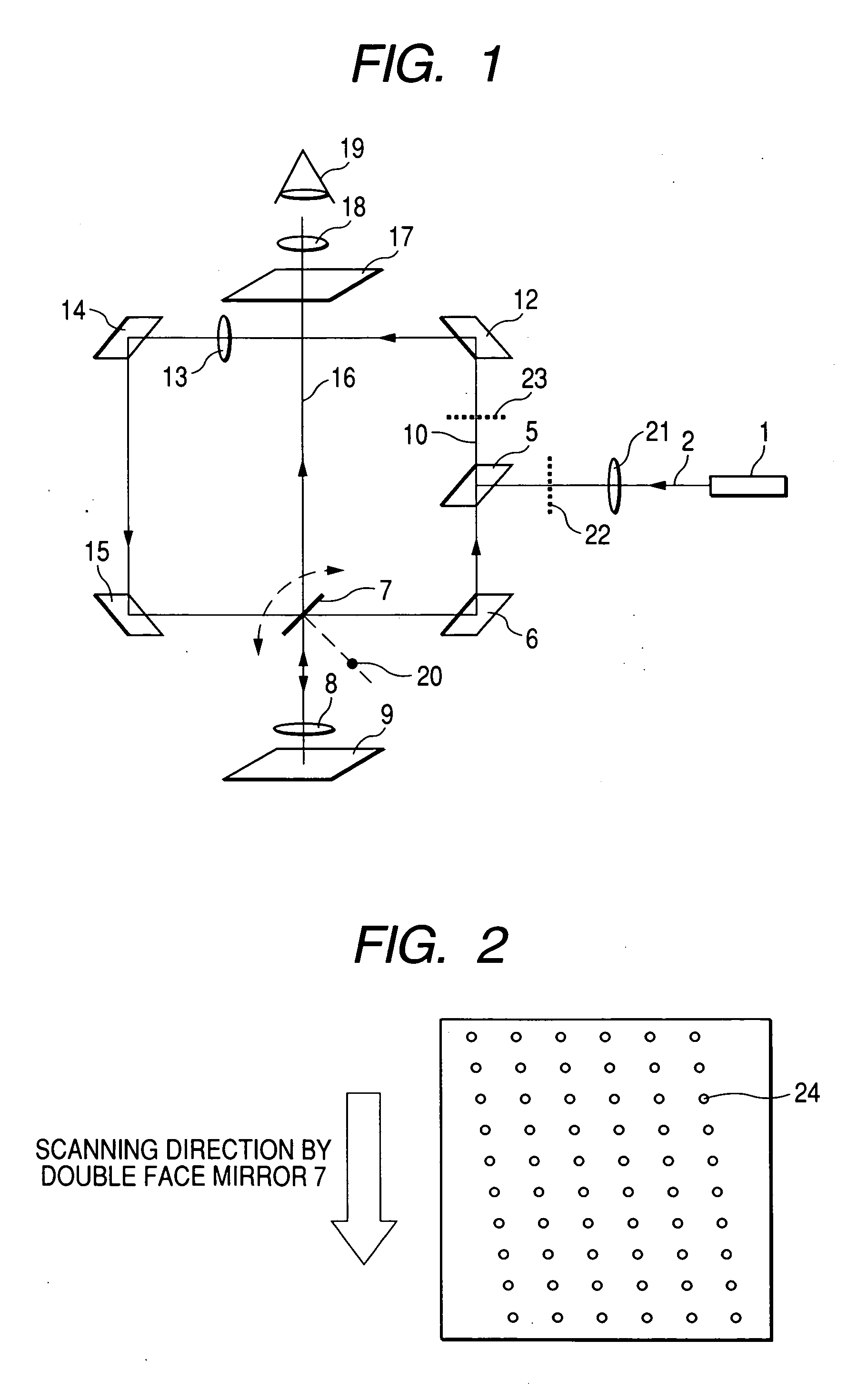
[0049]FIG. 1 is a configuration view showing a first embodiment of a confocal microscope according to the invention. Constituent elements similar to those of the previous drawing are attached with similar notations, and an explanation of the portions will be omitted.

[0050] The confocal microscope of the first embodiment shown in FIG. 1 is different from the confocal microscope of the related art shown in FIG. 10 in that an illumination light multipinhole array 22 substitutes for the illumination light slit 4, an observation light multipinhole array 23 substitutes for the observation light slit 11, and an optical element 21 for expanding light ray is disposed on an optical path between the illumination light multipinhole array 22 and the light source 1.

[0051] The optical element 21 for expanding light ray is a two-dimensional beam expander combined with, for example, a convex lens for enlarging a sectional area of light ray of the illumination light 2 emitted from the light source ...

second embodiment

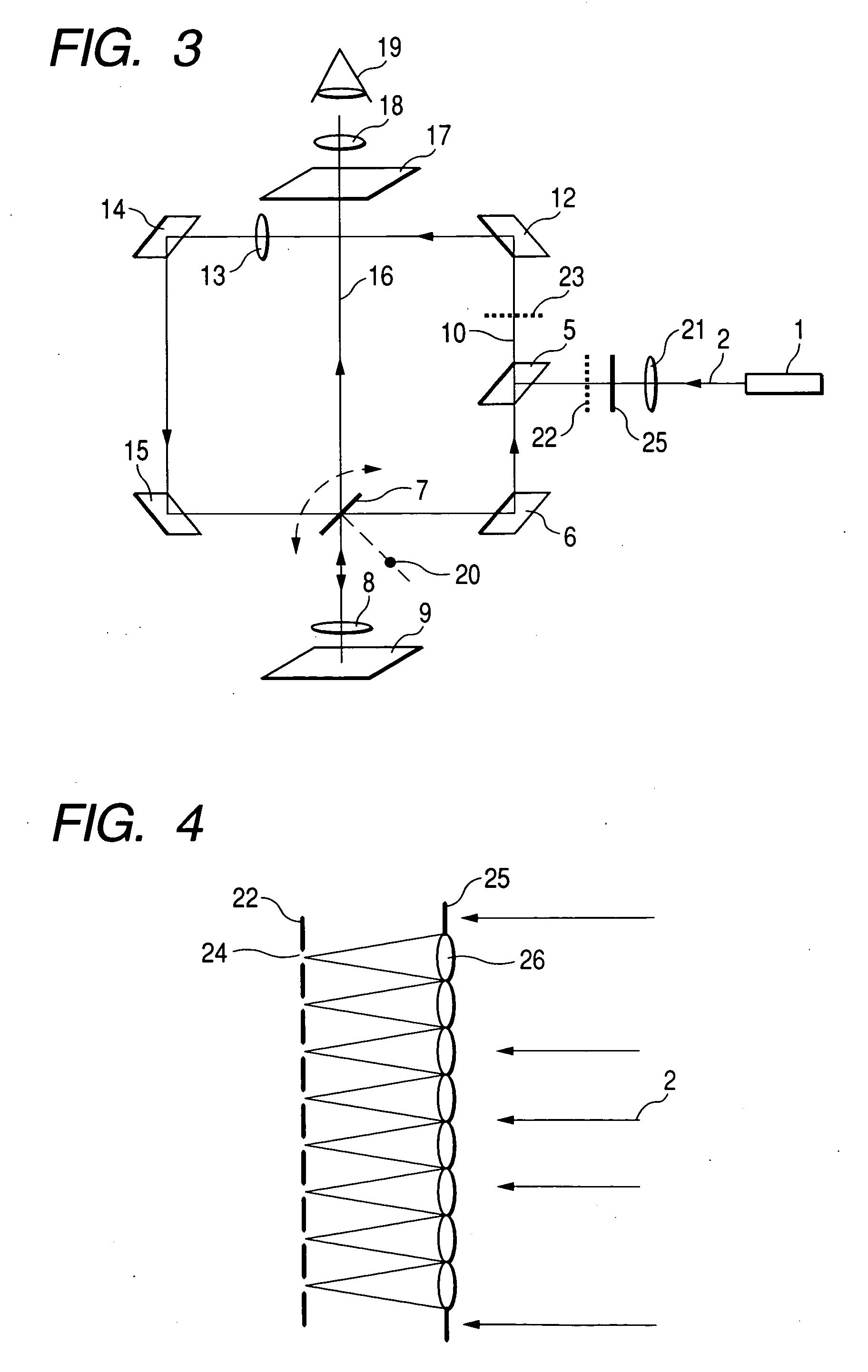
[0056]FIG. 3 is a configuration view showing a second embodiment of a confocal microscope according to the invention. Constituent elements similar to those of the previous drawings are attached with the similar notations, and an explanation thereof will be omitted.

[0057] The confocal microscope of the second embodiment shown in FIG. 3 is different from the confocal microscope of the first embodiment shown in FIG. 1 in that a multimicrolens array 25 is disposed on an optical path between the light ray expanding optical element 21 and the illumination light multipinhole array 22.

[0058]FIG. 4 is a view showing an example of a multimicrolens array applied to the confocal microscope of the invention. As shown by FIG. 4, the multimicrolens array 25 includes microlenses at positions in correspondence with the pinholes of the illumination light multipinhole array 22 and the microlenses 26 converge the illumination light 2 onto the pinholes 24. By converging the illumination light 2 onto t...

third embodiment

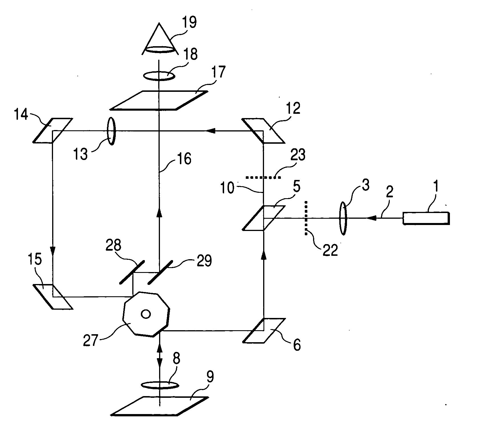
[0061]FIG. 6 is a configuration view showing a third embodiment of the confocal microscope according to the invention. Constituent elements similar to those of the previous drawings are attached with similar notations, and an explanation of the portions will be omitted.

[0062] The confocal microscope of the third embodiment in FIG. 6 is different from the confocal microscope of the first embodiment shown in FIG. 1 in that a polygonal mirror 27 substitutes for the double face mirror 7, and optical path bending mirrors 28, 29 are provided for adjusting the optical path in accordance therewith.

[0063] The polygonal mirror 27 is a polygonal prism having reflecting surfaces at side faces thereof. By rotating the polygonal prism around a center axis thereof, an angle of reflecting a beam incident on the side face is changed and a light converging point of a face of the observed sample is scanned. At the same time, the observation light 10 reflected from the mirror 15 is reflected by other...


PUM


Abstract

In A confocal microscope, a mirror reflects illumination light to focus on a focal point face of a sample through an object lens. The mirror is rotated to scan a focal point of the illumination light. A confocal image provided based on returned light from the sample. The confocal microscope has a first multipinhole array which has a plurality of pinholes, and to which light emitted from a light source is illuminated, and a second multipinhole array which has a plurality of pinholes, and intercepts light from other than the focal point face out of the returned light from the sample. The first multipinhole array functions as a plurality of point light sources, and the illumination light is light which passes through the pinholes of the first multipinhole array.

Description

CROSS-REFERENCE TO RELATED APPLICATIONS [0001] This application is based upon and claims the benefit of priority from the prior Japanese Patent Applications No. 2004-293278, filed on Oct. 6, 2004, the entire contents of which are incorporated herein by reference. BACKGROUND OF THE INVENTION [0002] 1. Field of the Invention [0003] The present invention relates to a confocal microscope, in details, relates to a confocal microscope which scans laser light by rotating a mirror to provide a confocal image of a sample. [0004] 2. Description of the Related Art [0005] A confocal microscope is for observing a sample by acquiring an image by scanning a converged light point on the sample and focusing returned light from the sample and is used for observing a physiological reaction of a live cell or observing morphology thereof in a field of a living body, biotechnology or the like or observing a surface of LSI in a semiconductor market. [0006]FIG. 10 is a configuration view showing an example...

Claims


Application Information

Patent Timeline
Patent Type & Authority Applications(United States)
IPC IPC(8): G02B21/06
CPCG02B21/0032G02B21/0044G02B21/0048G02B21/0084
Inventor AKIYAMA, TAKASHIMIKURIYA, KENTAKOSUGI, YASUHITO
Owner YOKOGAWA ELECTRIC CORP
Why Eureka
Try Eureka