Electrical power distribution system

a technology of electric power distribution system and power distribution circuit, which is applied in the integration of power network operation system, coupling device connection, instruments, etc., can solve the problems of product life cycle fatigue, smaller wires are not adequately protected by branch circuit breakers or fuse protection, and overload of smaller diameter wires in extension cords,

Inactive Publication Date: 2006-04-06
2D2C
View PDF26 Cites 73 Cited by
  • Summary
  • Abstract
  • Description
  • Claims
  • Application Information

AI Technical Summary

Problems solved by technology

Typically, these smaller wires are not adequately protected by the branch circuit breakers or fuses.
Overloads on smaller diameter wires in extension cords, lamps and other electrical devices can be the result of various causes, for example, improper product design, product life cycle fatigue, product abuse, excessive motor loads, physical damage to the wires, or high AC line voltage.
In North America alone, overloads on smaller diameter wires cause thousands of fires every year.
Extension cords are often improperly matched to the appliance load.
Where the current flowing through an extension cord exceeds the extension cord's current rating, overheating of the internal conductors in the extension cord results and such overheating can cause burning of cord insulation and materials adjacent to the extension cord, resulting in fires.
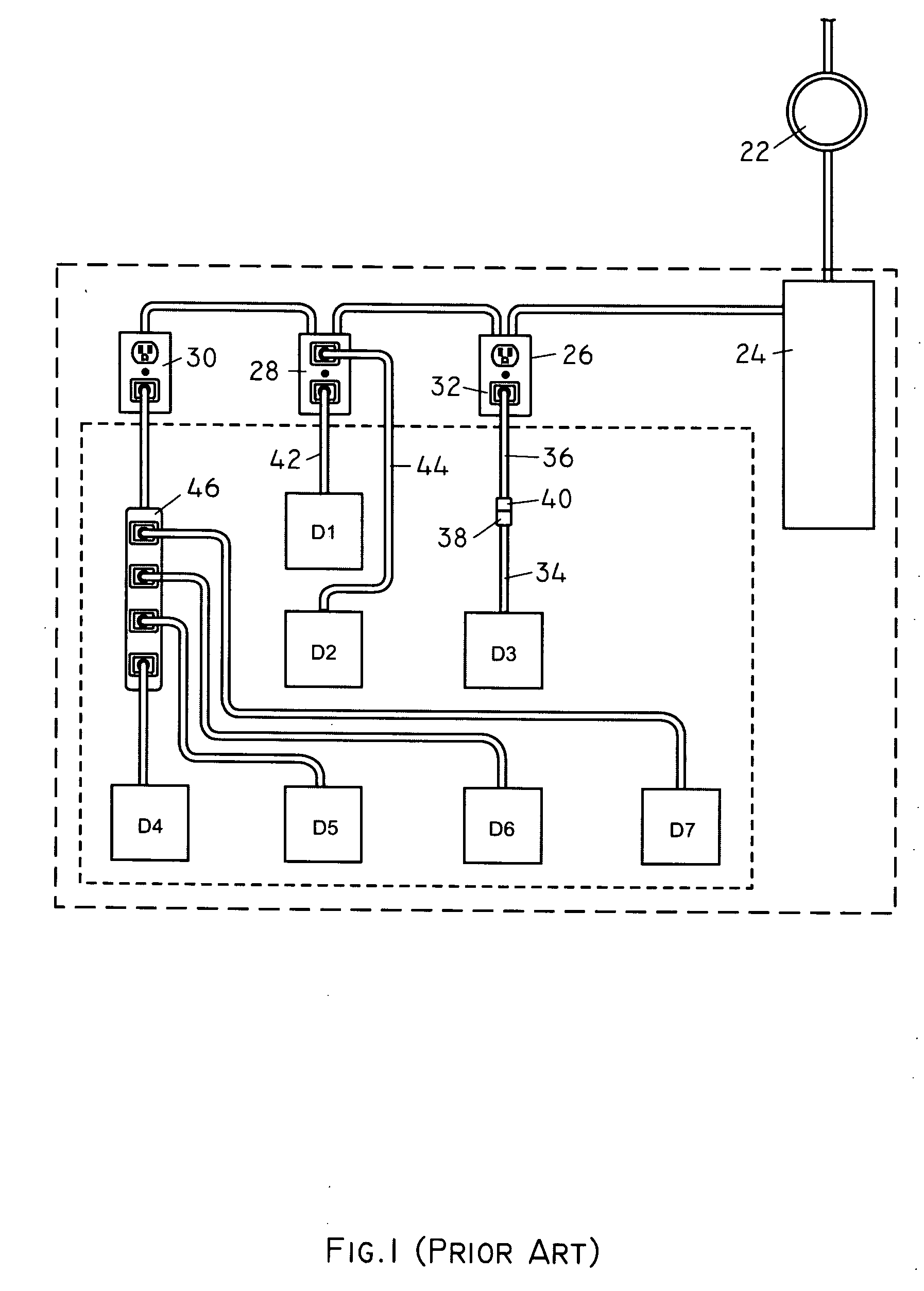
As is known in the art, electrical devices D4-D7 can easily cause the circuit including the outlet 30 to overload, eventually resulting in a fire hazard.
In these circumstances, because the current rating of the extension cord is exceeded, the conductors therein can overheat and cause a fire.
In this example, therefore, it can be seen that even though the building electrical system, power strip, and each appliance may comply with applicable safety codes respectively, a fire can result from their use, because of how they are used together.
In particular, it should be noted that the current overload protection provided by the circuit breaker does not help to avoid a fire in this example.
Other current overload faults can develop in other situations where the conventional overload protection provided by circuit breakers or fuses fails to prevent a fire.
For instance, electrical appliances such as televisions, refrigerators, toasters, computers and the like can, and often do, develop internal faults that cause a “hot spot” within the appliance.
With use over an extended time period, the bearings or bushings wear, and, eventually, lose lubrication.
This total current can exceed the current rating of the electrical cord of the appliance but still be insufficient to trip the relevant circuit breaker or fuse.
Accordingly, this can result in a fire, because the cord overheats.
Also, many appliances include combustible materials internally, which can ignite as a result of current overload.
In addition, improperly installed circuit breakers or fuses can allow unprotected overloads of in-wall wiring, electrical outlets, extension cords, or appliances.
For example, if a 20-ampere circuit breaker or fuse is inadvertently installed on a standard branch circuit (i.e., wired with 14 gauge copper wire, typically rated for 15 amperes of current), then overloads can occur throughout the electrical system without proper protection, resulting in overheated wires and, possibly, fire.
In North America alone, thousands of persons require treatment for electrical shocks and many people die of electrocution due to contact with these line voltages.
Power distribution systems are subject to voltage variations due to device load switching and environmental changes such as lightning.
Over-stressed grids can lead to brown-out and black-out conditions.
These various factors often result in power quality aberrations such as unexpected surges in line voltage, lower than acceptable line voltage, and higher than acceptable line voltage.
However, longer duration, high energy surges can destroy the MOVs and remove the protection.
Additionally, high and low line conditions can stress electrical devices and shorten their lives.

Method used


Image

  • Electrical power distribution system
  • Electrical power distribution system
  • Electrical power distribution system

Examples


Embodiment Construction

)

[0094] The present invention may be understood more readily by reference to the following detailed description of the invention and the examples provided herein. It is to be understood that the aspects described below are not limited to specific circuits, outlets, receptacles, plugs, or devices, and as such may, of course, vary. It is also to be understood that the terminology used herein is for the purpose of describing particular aspects only and is not intended to be limiting.

[0095] In this specification and in the claims that follow, reference will be made to a number of terms that shall be defined to have the following meanings.

[0096] Articles: As used in the specification and the appended claims, the singular forms “a”, “an” and “the” include plural references unless the context clearly dictates otherwise.

[0097] About: Often, ranges are expressed herein as from “about” one particular value, and / or to “about” another particular value. When such a range is expressed, another...


PUM


Abstract

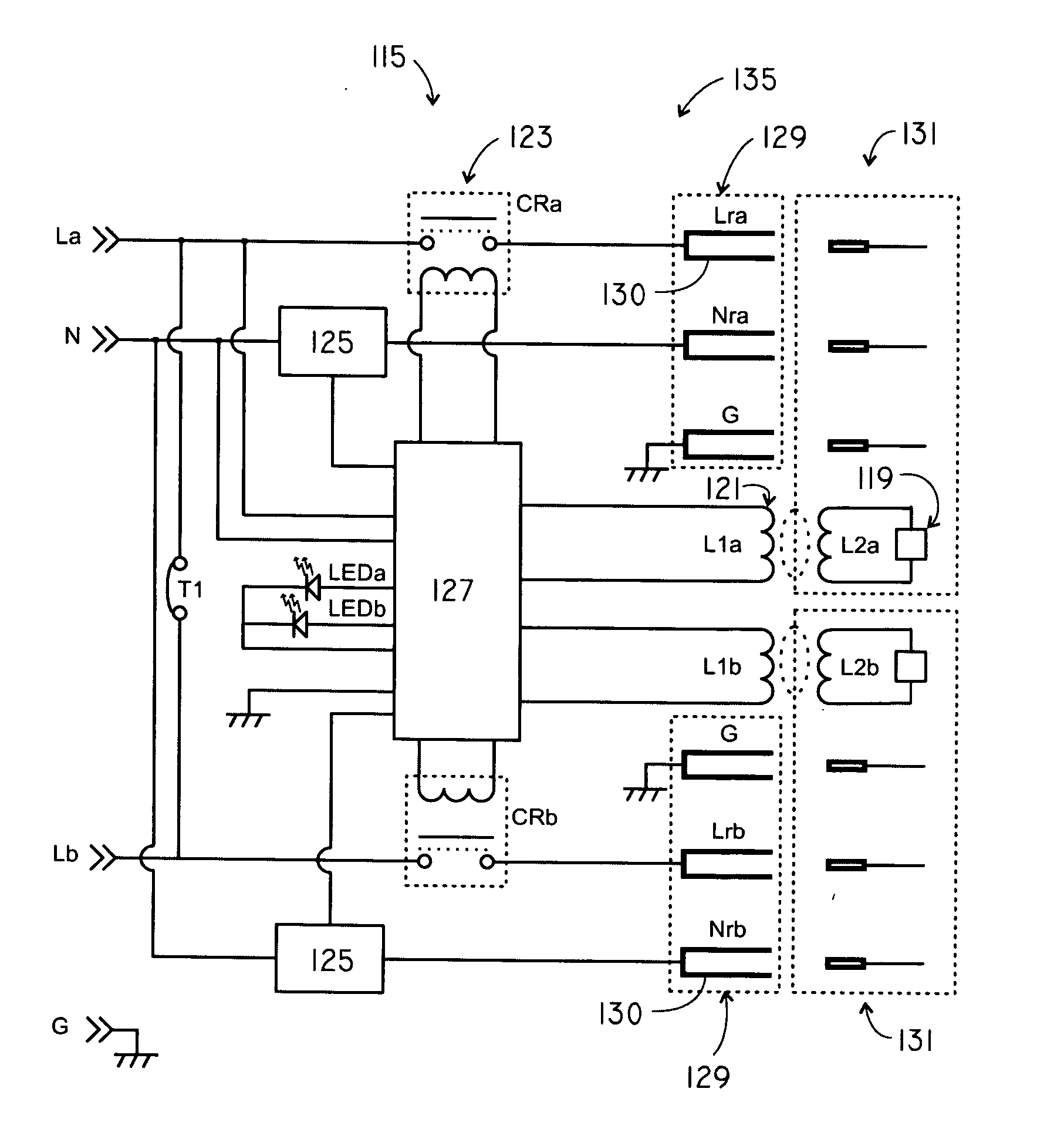
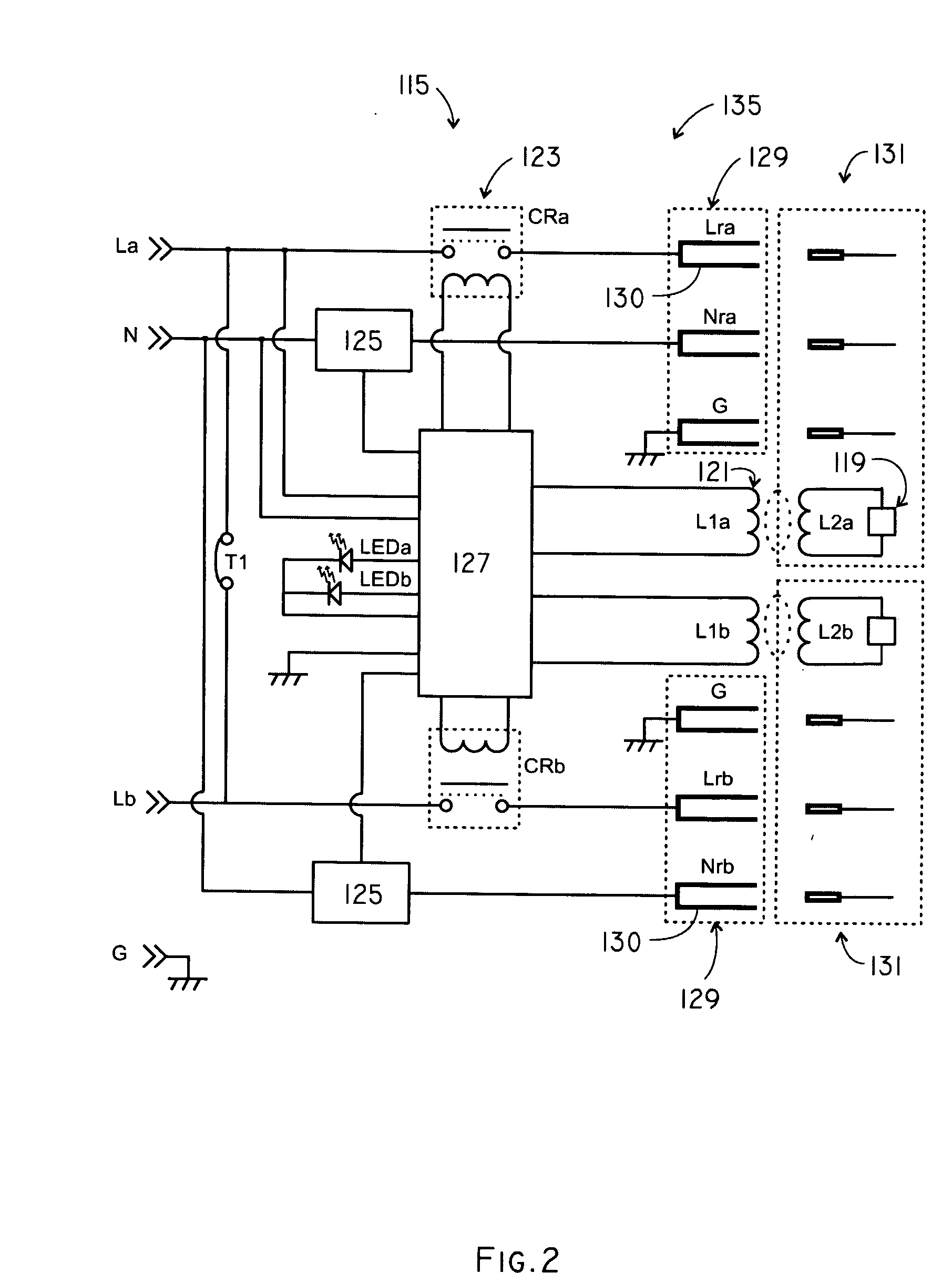
An electrical power distribution system for connecting an electrical device to a source of electrical power and disconnecting the electrical device therefrom. The system includes a PCD tag associated with the electrical device, and a PCD reader associated with a receptacle electrically connectable to the source of electrical power. The PCD tag has a PCD tag memory in which data related to the electrical device is stored in a format readable by the PCD reader, the data including an electrical device load rating. The system also has a switch device for connecting and disconnecting the receptacle to the power source. In addition, the system has a measuring device for measuring actual load and a control circuit for comparing actual load to the electrical device load rating. The control circuit provides a disconnect signal to the switch device upon the actual load exceeding the electrical device load rating.

Description

[0001] This application claims the benefit of U.S. Provisional Application No. 60 / 616,188, filed on Oct. 5, 2004.FIELD OF THE INVENTION [0002] This invention is related to electrical power distribution systems. BACKGROUND OF THE INVENTION [0003] AC electrical distribution systems are widely used in residential and commercial settings. Typically, wall-mounted (or otherwise) AC electrical outlets, sockets, or receptacles are provided with which AC electrical appliances are connected. For example, a typical residential electrical power distribution system 20 of the prior art is schematically illustrated in FIG. 1. (As will be described, the remainder of the drawings illustrate the present invention.) The system 20 includes a meter 22 electrically connected to a source of electrical power (not shown). Connected to the meter is a circuit breaker panel 24 (or fuse box). The panel 24 includes a plurality of circuit breakers (or fuses, as the case may be). As is known in the art, electrical...

Claims


Application Information

Patent Timeline
Patent Type & Authority Applications(United States)
IPC IPC(8): H02H3/08
CPCG06K19/07758H01H2300/03H01R13/7039H01R13/7135H02H1/0015H02H3/006H02H3/08Y04S20/14Y02B70/3241Y02B90/224Y04S20/227Y02B90/20Y02B70/30Y04S20/20
Inventor JONES, NICOLASMONTGOMERY, STEVESIMPSON, RICHARDBAKER, GREGORY
Owner 2D2C
Why Eureka
Try Eureka