
Minimizing handoffs and handoff times in wireless local area networks

Active Publication Date: 2006-04-06
TELOGY NETWORKS
View PDF7 Cites 73 Cited by
  • Summary
  • Abstract
  • Description
  • Claims
  • Application Information

AI Technical Summary

Benefits of technology

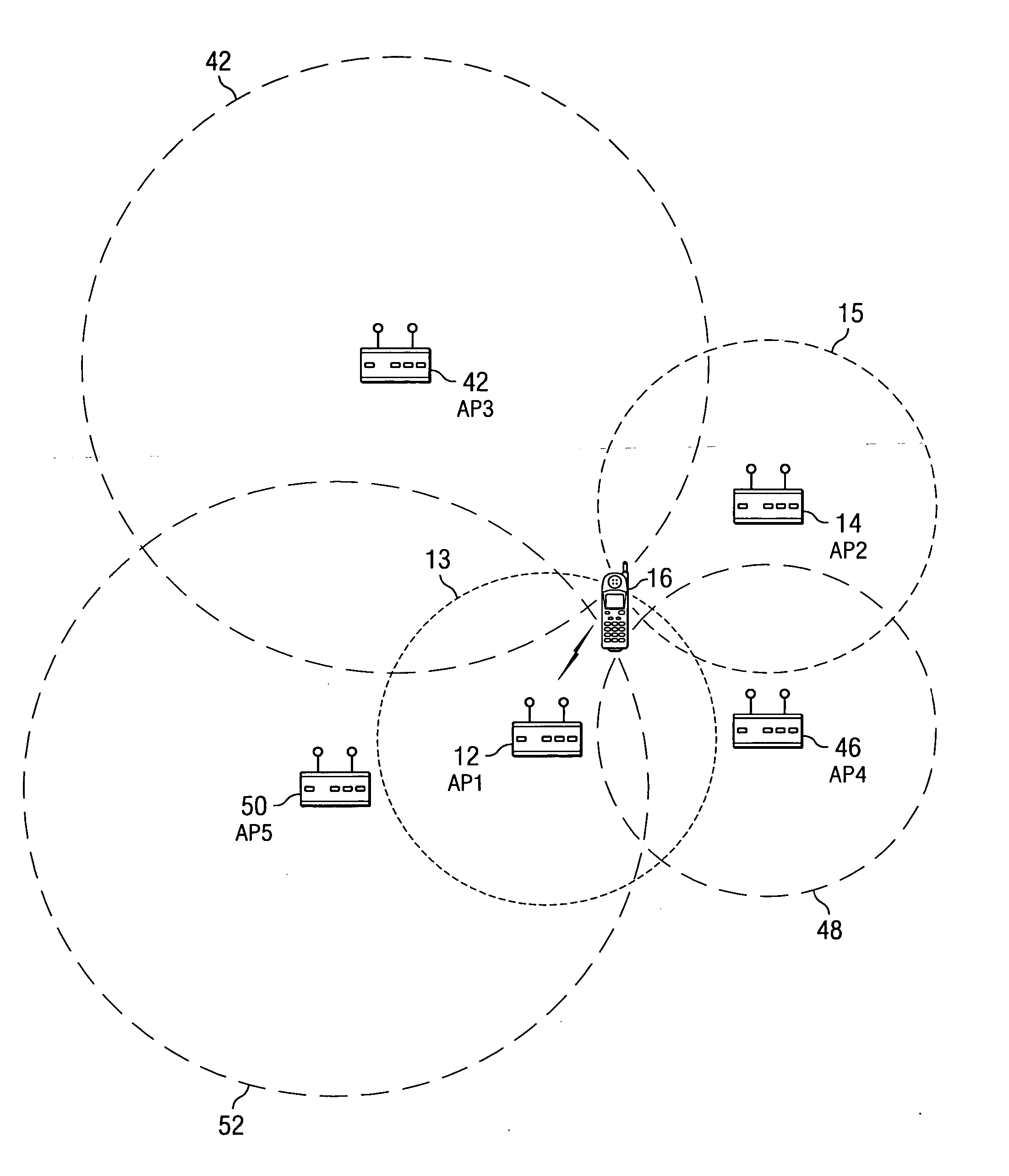
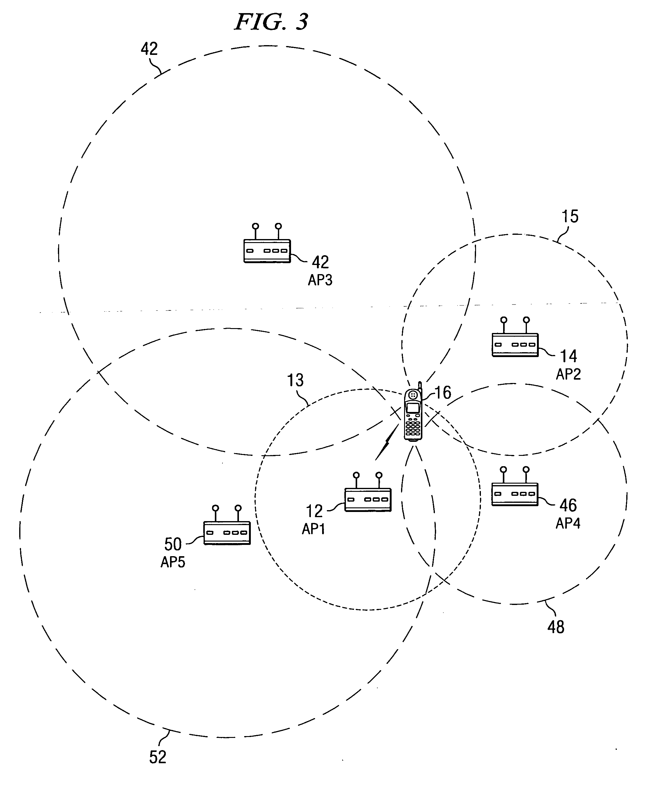
[0011] The above problems identified with the prior art are overcome with a technique for reducing the number of channels that are scanned during a handoff situation by tracking past user movements to select the posterior AP. A suitable sequence of channels to be scanned is generated in a memory table so that the number of handoffs are reduced and the average time during a handoff is reduced. To reduce handoffs and handoff latencies, the principle of locality (user movement patterns tend to be repetitive) is used. By tracking the past handoffs, future handoffs are predicted.
[0012] Two special cases are addresses in the technique for reducing handoff times. The first case is for coping with changes in user-movement patterns over time. A technique to predict the probability of a future handoff is enhanced by limiting the importance given to any one AP. Further, the technique is enhanced to compensate for additions of new APs or the removal of existing APs.
[0013] An alternative embodiment reduces the number of handoffs that occurs for a STA in an 802.11 WLAN. In this embodiment, each STA keeps a record of the time it has spent (e.g., “TS”) in association with the last three APs that it has been connected to. When the STA is about to perform a handoff from STA compares the saved values of time spent from the potential APs for a handoff. If one of the APs has a low time spent value, that is a transitional AP and the STA could probably have switched from the prior AP to the posterior AP directly, thus saving a handoff.

Problems solved by technology

However, VoIP over WLAN presents a unique set of problems that must be addressed prior implementing this technology.
A problem with handoffs, however, occurs with latency during the handoff process.
There are two problems with this approach.
First, scanning all channels every time a handoff is needed consumes a considerable amount of time.
Selecting an AP simply because it has the highest signal strength will not always yield expected results for seamless networking, since ESSs are usually designed with a bit of overlap to provide uninterrupted connectivity.

Method used


Image

  • Minimizing handoffs and handoff times in wireless local area networks
  • Minimizing handoffs and handoff times in wireless local area networks
  • Minimizing handoffs and handoff times in wireless local area networks

Examples


Embodiment Construction

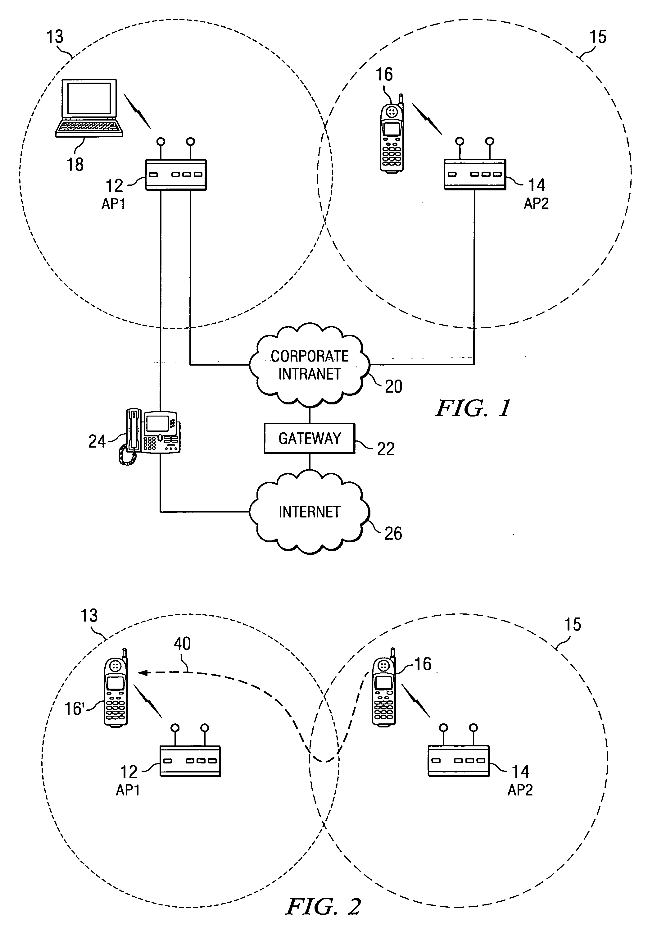
[0021] The preferred embodiment of the present invention includes a technique for reducing the handoff times to prevent delay in packet transmissions on a wireless local area network (WLAN) and reducing the number of handoffs wire a wireless endpoint station (STA) between access points (APs). One implementation of the preferred embodiment is on an IEEE (Institute of Electronic and Electrical Engineers) 802.11 WLAN. An 802.11b WLAN network is a highly dynamic environment because of the inherent dynamics of the wireless medium, low operating power of 802.11, and operation in the 2.4 GHz range. Since the 802.11b operates at low power (to save power and increase battery lifetimes), a geographically smaller BSS with multiple APs (Access Points) leads to frequent handoffs and roaming scenarios. Further, since 802.11b networks operate in the unlicenced frequency range of 2.4 GHz, it is potentially open to interference from other devices (e.g., microwaves, cordless phones, Bluetooth WLANs)....


PUM


Abstract

A method for reducing the number of channels that are scanned during a handoff situation for a wireless endpoint station in a wireless local area network (WLAN), such as an IEEE 802.11 network, by tracking past user movements within the WLAN. A suitable sequence of channels to be scanned is generated so that reduce the number of handoffs are reduced and the average time during a handoff is reduced. To reduce handoffs and handoff latencies, the principle of locality (user movement patterns tend to be repetitive) is used. By tracking the past handoffs, future handoffs are predicted.

Description

CROSS-REFERENCE TO RELATED APPLICATIONS [0001] None FIELD OF THE INVENTION [0002] The present invention relates generally to transmitting voice data over a wireless local area network (WLAN). More specifically, the present invention relates to reducing handoff time and the number of handoffs when a wireless endpoint station moves around an Extended Service Set (ESS). BACKGROUND OF THE INVENTION [0003] WLANs (Wireless Local Area Networks) utilize RF (Radio Frequency) signals or light signals to connect mobile endpoints to each other or to a centralized gateway and transmit data over a wireless medium between the physical endpoints or between a mobile endpoint and an endpoint on a network that is connected to the WLAN. In 1997 the IEEE published standards for WLANs under the title of 802.11 (also known as “Wi-Fi”). The IEEE 802.11b protocol has gained popularity over the past few years and deployment of 802.11b networks is expected to increase significantly in the near future. Current...

Claims


Application Information

Patent Timeline
IPC IPC(8): H04Q7/00H04W36/08H04W48/16H04W84/14
CPCH04W36/245H04W84/14H04W84/12H04W36/008375
Inventor CHANDRA, PRAPHULSINDHWANI, MANOJLIDE, DAVID
Owner TELOGY NETWORKS
Learn More