Radio communication system

a radio communication and wireless communication technology, applied in the field of wireless communication systems, can solve the problem of more power consumption of terminals

Inactive Publication Date: 2006-04-06
SONY CORP
View PDF6 Cites 121 Cited by
  • Summary
  • Abstract
  • Description
  • Claims
  • Application Information

AI Technical Summary

Benefits of technology

[0018] According to a further embodiment of this invention, as claimed in claim 10 thereof, there is provided a processing method for use with a terminal which has power-saving mode involving operations more energy-efficient than normal operations, the processing method including the steps of: starting to receive a physical layer frame including an upper layer frame relative to an upper layer above a physical layer; calculating a power-saving operation time in accordance with a length of the upper layer frame extracted from a header of the physical layer frame; after detecting a destination address from a header of the upper layer frame upon receipt thereof and determining that the upper layer frame is not destined for the terminal, giving an instruction for transition into the power-saving mode starting from the beginning of a body of the upper layer frame; and upon elapse of the power-saving operation time calculated in response to the instruction for transition into the power-saving mode, giving an instruction to cancel the power-saving mode. An effect of this embodiment is that it allows the terminal to operate in power-saving mode based on relevant information derived from the header of the physical layer frame under existing standards.
[0019] As claimed in claim 11 of this invention, a preferred variation of the embodiment of claim 10 thereof is the processing method further including the step of inhibiting the transition into the power-saving mode regardless of the instruction if information derived from the physical layer frame fails to comply with a predetermined condition. An effect of this preferred variation is that it inhibits the terminal from getting into power-saving mode if the prescribed condition is not met.
[0020] According to an even further embodiment of this invention, as claimed in claim 12 thereof, there is provided a program for causing a terminal having power-saving mode involving operations more energy-efficient than normal operations to carry out a procedure including the steps of: starting to receive a physical layer frame including an upper layer frame relative to an upper layer above a physical layer; calculating a power-saving operation time in accordance with a length of the upper layer frame extracted from a header of the physical layer frame; after detecting a destination address from a header of the upper layer frame upon receipt thereof and determining that the upper layer frame is not destined for the terminal, giving an instruction for transition into the power-saving mode starting from the beginning of a body of the upper layer frame; and upon elapse of the power-saving operation time calculated in response to the instruction for transition into the power-saving mode, giving an instruction to cancel the power-saving mode. An effect of this embodiment is that it allows the terminal to operate in power-saving mode based on relevant information derived from the header of the physical layer frame under existing standards.
[0021] As claimed in claim 13 of this invention, a preferred variation of the embodiment of claim 12 thereof is the program wherein the procedure may further include the step of inhibiting the transition into the power-saving mode regardless of the instruction if information derived from the physical layer frame fails to comply with a predetermined condition. An effect of this preferred variation is that it inhibits the terminal from getting into power-saving mode if the prescribed condition is not met.
[0022] According to a still further embodiment of this invention, as claimed in claim 14 thereof, there is provided a storage medium which stores a program in a manner readable by a computer for execution, the program causing a terminal having power-saving mode involving operations more energy-efficient than normal operations to carry out a procedure including the steps of: starting to receive a physical layer frame including an upper layer frame relative to an upper layer above a physical layer; calculating a power-saving operation time in accordance with a length of the upper layer frame extracted from a header of the physical layer frame; after detecting a destination address from a header of the upper layer frame upon receipt thereof and determining that the upper layer frame is not destined for the terminal, giving an instruction for transition into the power-saving mode starting from the beginning of a body of the upper layer frame; and upon elapse of the power-saving operation time calculated in response to the instruction for transition into the power-saving mode, giving an instruction to cancel the power-saving mode. An effect of this embodiment is that it allows the terminal to operate in power-saving mode based on relevant information derived from the header of the physical layer frame under existing standards.
[0023] As claimed in claim 15 of this invention, a preferred variation of the embodiment of claim 14 thereof is the storage medium wherein the procedure may further include the step of inhibiting the transition into the power-saving mode regardless of the instruction if information derived from the physical layer frame fails to comply with a predetermined condition. An effect of this preferred variation is that it inhibits the terminal from getting into power-saving mode if the prescribed condition is not met.

Problems solved by technology

In fact, in a wireless LAN setup, terminals tend to consume more power because communications take place whenever data sent from an access point or any one terminal is received by each terminal.

Method used


Image

  • Radio communication system
  • Radio communication system
  • Radio communication system

Examples


Embodiment Construction

[0040] Preferred embodiments of this invention will now be described in detail with reference to the accompanying drawings.

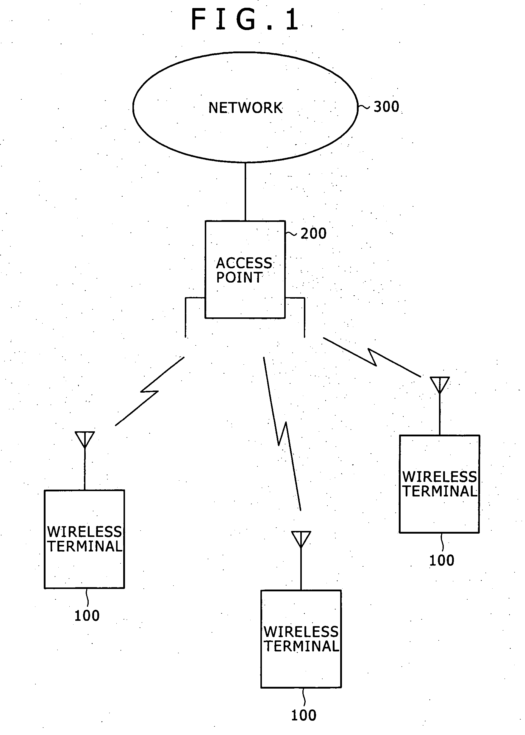
[0041]FIG. 1 is a schematic view showing a typical configuration of a wireless communication system embodying this invention. In this example, an access point 200 is wired to a network 300, and a plurality of wireless terminals 100 are connected wirelessly to the access point 200. The access point 200 and wireless terminals 100 constitute a wireless LAN that is distinct from the network 300. The setup in which a network is formed by an access point is called an infrastructure mode.

[0042] Although the example of FIG. 1 shows only one wireless LAN, a plurality of access points 200 may be connected to the network 300 in practice. In such a case, a wireless terminal 100 as part of a first wireless LAN may communicate with another wireless terminal 100 belonging to a second wireless LAN by way of the access point 200 of the first LAN, via the network 300, and throu...


PUM


Abstract

A sleep length calculation unit 410 of a terminal calculates a sleep length based on what is contained in a PLCP header of a frame, and sets the calculated length on a timer 430. An address detection unit 420 of the terminal detects a destination address from inside a MAC header of the frame to see if this frame is destined for another terminal. If the frame is found destined for another terminal, then this terminal gives a power supply unit 180 an instruction to start sleeping while causing the timer 430 to start counting time. When the sleep length is found to have elapsed on the timer 430, the terminal gives the power supply unit 180 an instruction to stop sleeping. If what is contained in the PLCP header or MAC header is not deemed reliable, then a sleep inhibit determination unit 440 inhibits the power supply unit 180 from going to sleep. The structure allows a wireless communication system to effect a transition into power-saving mode upon acquiring necessary information, without making changes to existing standards.

Description

TECHNICAL FIELD [0001] The present invention relates to a wireless communication system. More particularly, the invention relates to a wireless communication system with terminals arranged to operate in power-saving fashion, a processing method for use with these terminals, a program for causing a computer to carry out that processing method, and a storage medium which stores that program in a computer-readable manner. BACKGROUND ART [0002] Wireless communication systems are each made up of component terminals communicating with one another wirelessly. One such system is the wireless LAN (local area network) gaining widespread use by replacing conventional wired LANs. There exist a number of standards for the wireless LAN. The IEEE 802.11 standard stipulated by a working group under the IEEE (Institute of Electrical and Electronics Engineers) 802 standardization committee is known in particular for its provisions regarding the physical layer and a MAC (medium access control) sublaye...

Claims


Application Information

Patent Timeline
Patent Type & Authority Applications(United States)
IPC IPC(8): H04J3/24G06F1/32H04B1/16H04L12/28H04W52/02
CPCH04B1/1615H04W52/0225Y02B60/50Y02D30/70H04W52/02
Inventor OGISO, TAKAYUKIFUDUDA, KUNIO
Owner SONY CORP
Why Eureka
Try Eureka