
Multi-leaf collimator position sensing

a collimator and position sensing technology, applied in radiation therapy, instruments, therapy, etc., can solve the problems of complex treatment, insufficient field shape variability, and particularly great danger of proton beam therapy devices

Inactive Publication Date: 2006-04-06
SIEMENS MEDICAL SOLUTIONS USA INC
View PDF16 Cites 36 Cited by
  • Summary
  • Abstract
  • Description
  • Claims
  • Application Information

AI Technical Summary

Benefits of technology

The present invention relates to a system for calibrating radiation treatment devices, specifically collimators, used in radiation therapy. The technical effect of the invention is to provide a more accurate and efficient method for calibrating collimators, which can take into account the shape and volume of the tumor being treated, while minimizing damage to healthy tissue and organs. The current method of calibration, which involves using a light field, is subjective and time-consuming. The invention proposes an automatic calibration system that can be used with a variety of collimators and can provide a more accurate reference point for the calibration. This will improve the accuracy and efficiency of radiation therapy and increase the likelihood of successful treatment.

Problems solved by technology

This complicates treatment, because the healthy tissue and organs must be taken into account when delivering a dose of radiation to the tumor.
The danger is particularly great with proton beam therapy devices where the radiation dose delivered is higher and more focused than photon or electron beam therapy devices.
These solid jaw blocks, however, do not provide sufficient variability in the field shape.
This can be particularly difficult where the treatment beam is an X-ray beam.
It is also difficult to adjust the field shape where the treatment beam is an electron beam due to electron attenuation and scattering.
Delivery errors may occur if the light field is not located at a same position as the subsequently-produced radiation field.
Calibration fixtures may be mounted on the MLC, but the MLC could be damaged if they are not handled properly.
Other electronic automatic calibration may suffer from damaging exposure to radiation and thus, may be subject to error or failure.

Method used


Image

  • Multi-leaf collimator position sensing
  • Multi-leaf collimator position sensing
  • Multi-leaf collimator position sensing

Examples


Embodiment Construction

[0026] The following description is provided to enable any person of ordinary skill in the art to make and use the invention and sets forth the best modes contemplated by the inventor for carrying out the invention. Various modifications, however, will remain readily apparent to those in the art.

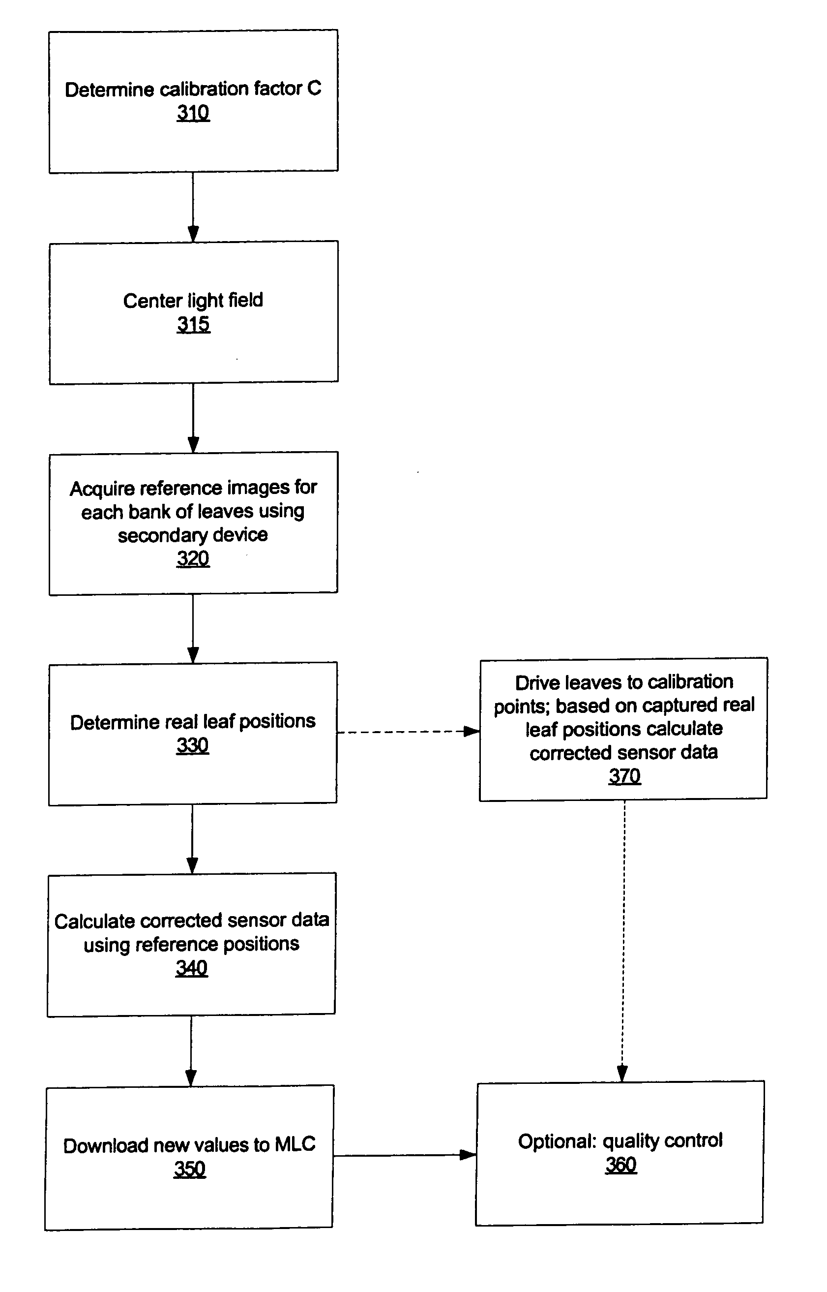
[0027] Some embodiments of the present invention provide a system, method, apparatus, and means to calibrate a multi-leaf collimator using a secondary image acquisition device such as a scanner to capture the shape of a projected light field on the patient bed. The calibration is based upon using the secondary image acquisition device to capture a series of reference image captures, uploading the capture data to a personal computer or image processing system, and determining calibration parameters and feeding such parameters to a control system to perform the actual adjustment of collimator leaves.

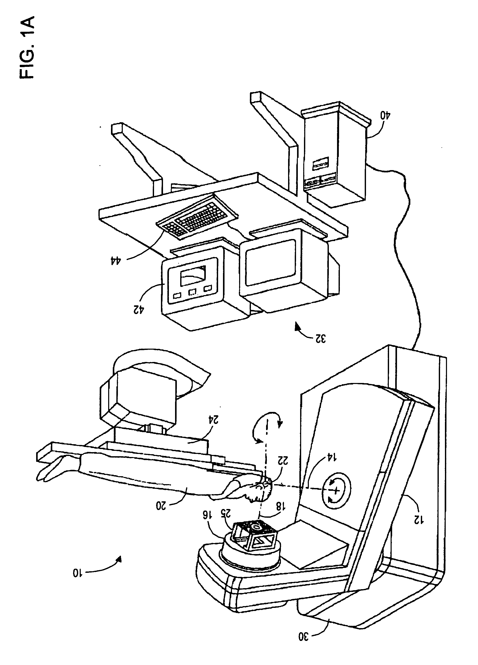
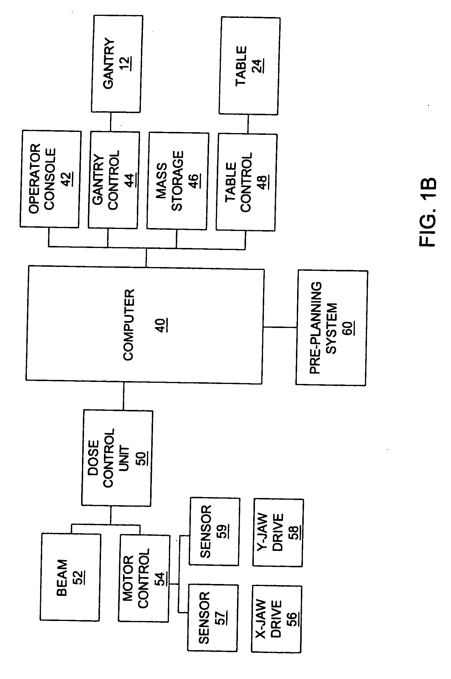
[0028] Referring first to FIG. 1A, a radiation therapy device 10 is shown in which embodiment...


PUM


Abstract

A method for determining real positions in a multi-leaf collimator (MLC) is disclosed. A scanner or other secondary imaging device is used to acquire a series of reference images and to capture the light field when the MLC is in a particular position and has a particular geometry. The reference images are used together with the captured light field images in order to determine the real positions of the leaves in the MLC. The real positions are used to correct any calibration problems in the mechanism used to drive the leaves of the MLC.

Description

BACKGROUND [0001] 1. Field of the Invention [0002] The present invention relates generally to radiation treatment, and more particularly to calibrating systems to be used during such treatment. [0003] 2. Related Art [0004] Conventional radiation treatment typically involves directing a radiation beam at a tumor in a patient to deliver a predetermined dose of treatment radiation to the tumor according to an established treatment plan. An exemplary radiation treatment device is described in U.S. Pat. No. 5,668,847, issued Sep. 16, 1997 to Hernandez. [0005] Tumors have three-dimensional treatment volumes which typically include segments of normal, healthy tissue and organs. Healthy tissue and organs are often in the treatment path of the radiation beam. This complicates treatment, because the healthy tissue and organs must be taken into account when delivering a dose of radiation to the tumor. While there is a need to minimize damage to healthy tissue and organs, there is an equally im...

Claims


Application Information

Patent Timeline
Patent Type & Authority Applications(United States)
IPC IPC(8): G06K9/36G06K9/00
CPCA61N5/1042
Inventor MARC, DELAPERRIERE
Owner SIEMENS MEDICAL SOLUTIONS USA INC
Learn More