Compression unit of orbiting vane compressor

a compressor and orbiting vane technology, applied in the direction of machines/engines, rotary/oscillating piston pump components, liquid fuel engines, etc., can solve the problems of deteriorating contact between the circular arc-shaped opening of the circular vane and the sealing means, and affecting the efficiency of the compressor. , to achieve the effect of convenient manufacturing

Inactive Publication Date: 2006-04-06
LG ELECTRONICS INC
View PDF13 Cites 5 Cited by
  • Summary
  • Abstract
  • Description
  • Claims
  • Application Information

AI Technical Summary

Benefits of technology

[0023] Therefore, the present invention has been made in view of the above problems, and it is an object of the present invention to provide a compression unit of an orbiting vane compressor having improved tight contact between a circular vane and sealing means, the sealing means being easily manufactured.

Problems solved by technology

However, it is very difficult to manufacture the circular arc-shaped slider of the sealing means such that the circular arc-shaped slider can perform a curved reciprocating movement in the annular space, while being tightly disposed in the opening, according to the orbiting movement of the circular vane.
Consequently, the tight contact between the circular arc-shaped opening of the circular vane and the sealing means is considerably deteriorated, and the seal between the compression chambers is also deteriorated.
Furthermore, the performance of the compressor is also deteriorated as the tight contact between the circular arc-shaped opening of the circular vane and the sealing means and the seal between the compression chambers are deteriorated.

Method used


Image

  • Compression unit of orbiting vane compressor
  • Compression unit of orbiting vane compressor
  • Compression unit of orbiting vane compressor

Examples


Embodiment Construction

[0056] Now, preferred embodiments of the present invention will be described in detail with reference to the accompanying drawings.

[0057]FIG. 4 is a cross-sectional view illustrating a compression unit of an orbiting vane compressor according to a first preferred embodiment of the present invention.

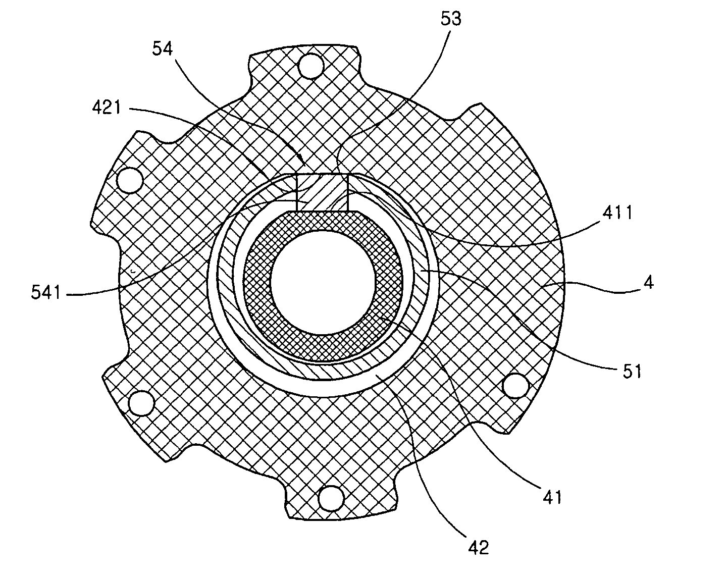
[0058] As shown in FIG. 4, the compression unit of the orbiting vane compressor according to the present invention comprises sealing means 54 that performs a linear reciprocating movement in an annular space defined in a cylinder while being tightly fitted in an opening formed at a circular vane 51 for maintaining the seal between a pair of compression chambers formed in the annular space 42 and, at the same time, maintaining the seal between suction chambers also formed in the annular space 42 and the compression chambers.

[0059] The sealing means 54 comprises a linear slider 541 disposed between a first horizontal contact surface 411 formed at an inner ring 41 of the cylinder 4 and a ...


PUM


Abstract

Disclosed herein is a compression unit of an orbiting vane compressor having improved tight contact between a circular vane and sealing means wherein the sealing means can be easily manufactured. The compression unit compresses refrigerant gas introduced by an orbiting movement of a circular vane in an annular space defined between the inner wall of a cylinder and an inner ring. The compression unit comprises a first horizontal contact surface formed at the outer circumferential surface of the inner ring, a second horizontal contact surface formed at the inner wall of the cylinder while being parallel with the first horizontal contact surface, and a linear slider disposed in an opening formed at the circular vane for performing a linear reciprocating movement along the first and second horizontal contact surfaces.

Description

BACKGROUND OF THE INVENTION [0001] 1. Field of the Invention [0002] The present invention relates to an orbiting vane compressor, and, more particularly, to a compression unit of an orbiting vane compressor having improved tight contact between a circular vane and sealing means wherein the sealing means can be easily manufactured. [0003] 2. Description of the Related Art [0004] Referring to FIG. 1, there is illustrated a conventional orbiting vane compressor. As shown in FIG. 1, a drive unit D and a compression unit P are mounted in a shell 1 while the drive unit D and the compression unit P are hermetically sealed. The drive unit D and the compression unit P are connected to each other via a vertical crankshaft 8, the upper and lower ends of which are rotatably supported by a main frame 6 and a subsidiary frame 7, such that power from the drive unit D is transmitted to the compression unit P through the crankshaft 8. [0005] The drive unit D comprises: a stator 2 fixedly disposed be...

Claims


Application Information

Patent Timeline
Patent Type & Authority Applications(United States)
IPC IPC(8): F01C1/02F16N13/20F01C1/063
CPCF04C18/02F05C2251/14
Inventor HWANG, SEON-WOONGYOO, DONG-WON
Owner LG ELECTRONICS INC
Why Eureka
Try Eureka