Orbiting vane compressor with side-inlet structure

a vane compressor and side-inlet technology, which is applied in the direction of liquid fuel engines, machines/engines, rotary piston liquid engines, etc., can solve the problems of reducing the volumetric efficiency of the compressor, deteriorating the compression performance of the compressor, and the inability to apply the conventional vane compressor, etc., to achieve the effect of increasing the sectional area of the refrigerant gas inlet outlet channel

Inactive Publication Date: 2006-04-06
LG ELECTRONICS INC
View PDF23 Cites 5 Cited by
  • Summary
  • Abstract
  • Description
  • Claims
  • Application Information

AI Technical Summary

Benefits of technology

[0016] It is another object of the present invention to provide an orbiting vane compressor having refrigerant gas inlet and outlet channels isolated from each other, thereby increasing the sectional area of the refrigerant gas inlet outlet channel.

Problems solved by technology

It is impossible, however, to apply the conventional vane compressor with the above-stated construction and operation as a refrigerant compressor used in a refrigerator or an air conditioner.
As a result, the refrigerant gas is introduced into the cylinder in a high-temperature and low-pressure state, which decreases the volumetric efficiency of the compressor.
Consequently, the compression performance of the compressor is deteriorated.
Consequently, it is impossible to increase the sectional area of the refrigerant gas inlet channel, which is necessary to reduce pressure loss.

Method used


Image

  • Orbiting vane compressor with side-inlet structure
  • Orbiting vane compressor with side-inlet structure
  • Orbiting vane compressor with side-inlet structure

Examples


Embodiment Construction

[0044] Now, preferred embodiments of the present invention will be described in detail with reference to the accompanying drawings.

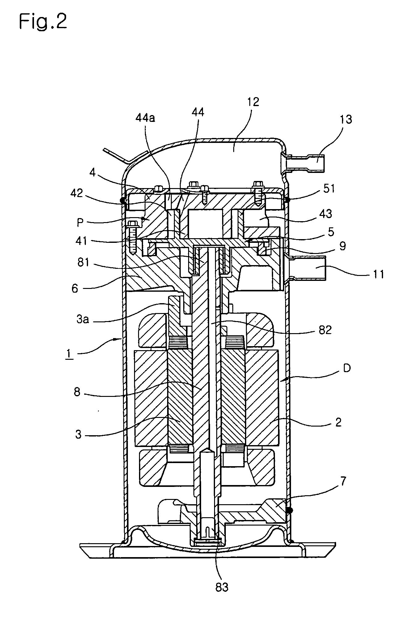
[0045]FIG. 2 is a longitudinal sectional view illustrating the overall structure of an orbiting vane compressor according to a first preferred embodiment of the present invention.

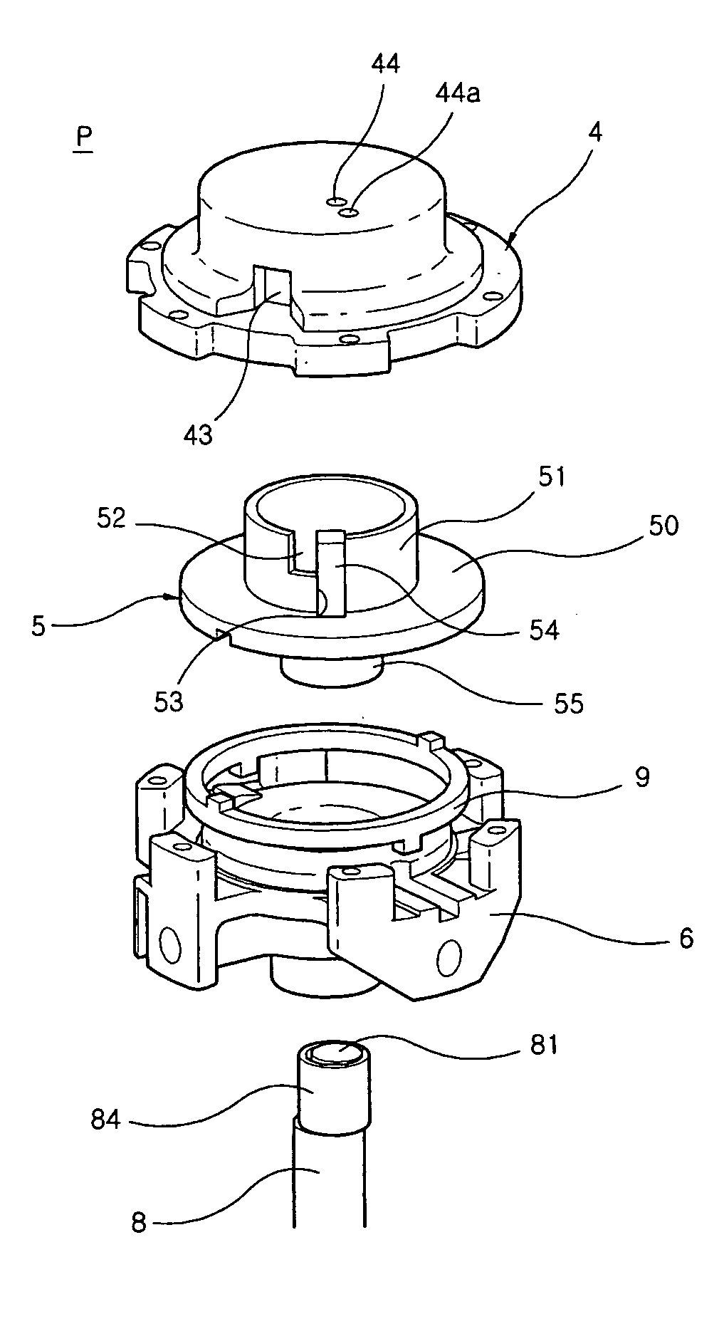
[0046] The orbiting vane compressor shown in FIG. 2 is a low-pressure type refrigerant compressor. As shown in FIG. 2, a drive unit D and a compression unit P are mounted in a shell 1 while the drive unit D and the compression unit P are hermetically sealed. The drive unit D and the compression unit P are connected to each other via a vertical crankshaft 8, the upper and lower ends of which are rotatably supported by a main frame 6 and a subsidiary frame 7, such that power from the drive unit D is transmitted to the compression unit P through the crankshaft 8.

[0047] The drive unit D comprises: a stator 2 fixedly disposed between the main frame 6 and the subsidiary frame 7; an...


PUM


Abstract

Disclosed herein is an orbiting vane compressor with a side-inlet structure that is capable of compressing air in a cylinder according to an orbiting movement of an orbiting vane, the orbiting vane compressor being applied to a refrigerant compressor having refrigerant gas inlet and outlet channels isolated from each other, thereby increasing the sectional area of the refrigerant gas inlet channel. Refrigerant gas is introduced into the cylinder from the side of the cylinder, is compressed in the cylinder, and is then discharged upward or downward out of the cylinder. As a result, refrigerant gas introduced into the cylinder through the refrigerant gas inlet channel is prevented from being heated by compressed refrigerant gas discharged through the refrigerant gas outlet channel.

Description

BACKGROUND OF THE INVENTION [0001] 1. Field of the Invention [0002] The present invention relates to an orbiting vane compressor, and, more particularly, to an orbiting vane compressor with a side-inlet structure that is capable of compressing air in a cylinder according to an orbiting movement of an orbiting vane while refrigerant gas inlet and outlet channels are isolated from each other and of increasing the sectional area of the refrigerant gas inlet channel. [0003] 2. Description of the Related Art [0004] Generally, a vane compressor compresses air introduced into a cylinder according to an orbiting movement of a vane. FIG. 1 is a longitudinal sectional view illustrating the structure of a conventional vane compressor. [0005] As shown in FIG. 1, the vane compressor comprises a compression unit 100 connected to a drive unit (not shown) via a rotary shaft 120. The compression unit 100 is hermetically sealed by upper and lower housings 110 and 110a. In the compression unit 100 is ...

Claims


Application Information

Patent Timeline
Patent Type & Authority Applications(United States)
IPC IPC(8): F01C20/18F16N13/20F04C2/00F01C1/02F03C4/00
CPCF04C18/04F04C23/008F04C2250/101F04C18/02F04C18/344F04C18/356
Inventor HWANG, SEON-WOONGYOO, DONG-WON
Owner LG ELECTRONICS INC
Why Eureka
Try Eureka