
Optical pickup device and optical disk device using it

a pickup device and optical disk technology, applied in the direction of data recording, instruments, carrier constructional parts disposition, etc., can solve the problems of reducing durability, reducing the performance, and heat not being able to be sufficiently conducted to the pickup case via fixing members, so as to improve the transmission path characteristics, the effect of reducing the risk of deterioration and reducing the cos

Inactive Publication Date: 2005-11-10
HITACHI MEDIA ELECTORONICS CO LTD
View PDF2 Cites 6 Cited by
  • Summary
  • Abstract
  • Description
  • Claims
  • Application Information

AI Technical Summary

Benefits of technology

[0012] An object of the present invention therefore is to provide an optical pickup device and an optical disk device both excellent in reliability, in which heat conduction from the semiconductor laser to the pickup case is increased thereby to prevent the semi conductor laser from deteriorating in performance, being reduced in durability and committing erroneous actions.

Problems solved by technology

The heat emission described above involves the risk of deteriorating the performance, reducing the durability and inviting erroneous actions of such components as the semiconductor laser and the laser drive circuit.
This results in the problem that the conduction of the heat generated by the semiconductor laser is obstructed by the adhesive, and the heat cannot be sufficiently conducted to the pickup case via fixing members.
In the aforementioned optical pickup according to Patent Reference 1, heat emitted from the integrated optical element is conducted to the cover and the slide base via the transmission path flexible substrate on which the integrated optical element is mounted, but it is still unable to achieve a sufficiently high level of heat conducting performance.
Thus the transmission path flexible substrate according to Patent Reference 1 involves a problem.
Namely, when heat conduction from the integrated optical element is needed, not only the substrate itself may also be electrified and emit heat to obstruct heat conduction from the integrated optical element to the cover and the slide base, but also, if any other heat emitting component is connected to the heat conduction side, the heat conduction performance of the integrated optical element will be deteriorated by the thermal influence of this additional heat source.

Method used


Image

  • Optical pickup device and optical disk device using it
  • Optical pickup device and optical disk device using it
  • Optical pickup device and optical disk device using it

Examples


second embodiment

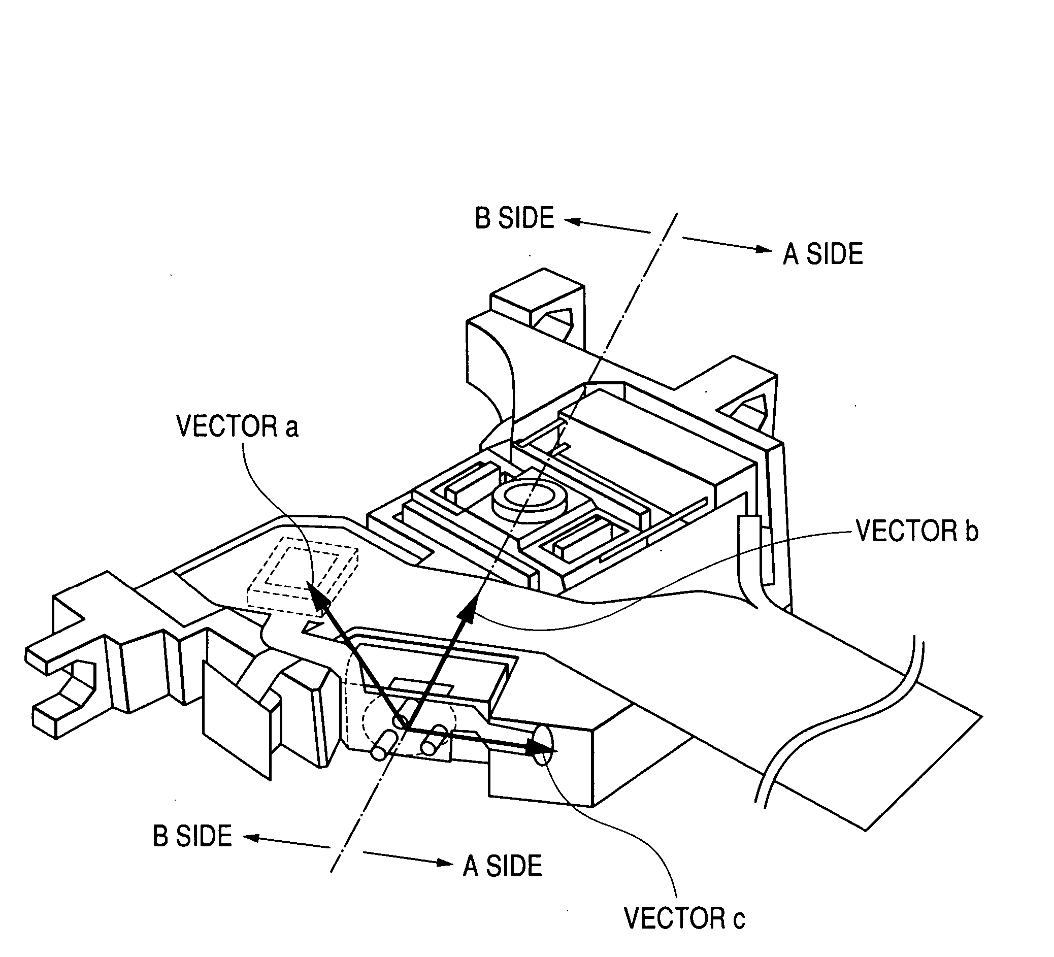
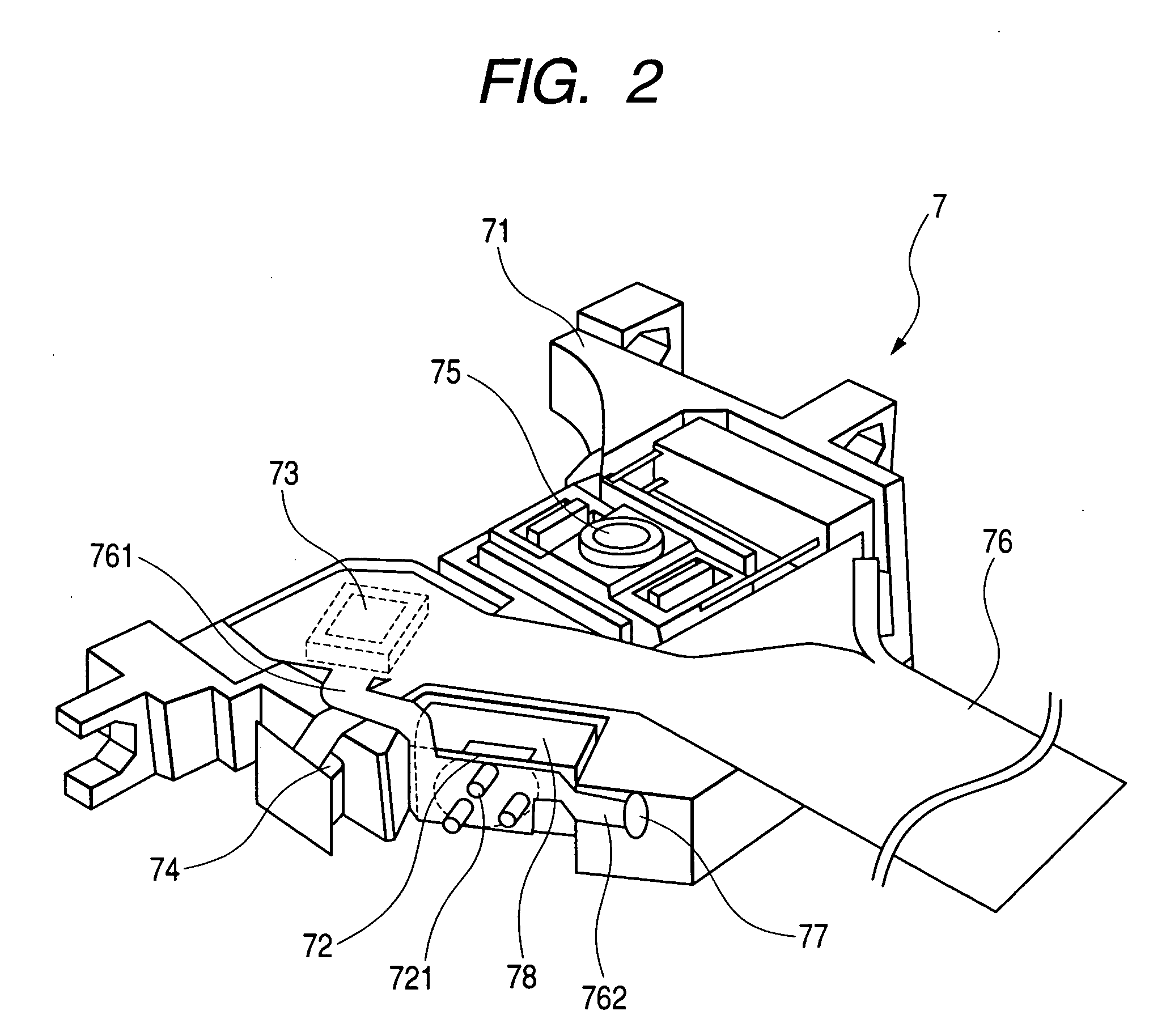
[0080] In the second embodiment shown in FIG. 7, the wiring pattern 763 of the heat conducting flexible substrate 762 which connects the grounding terminal 721 of the semiconductor laser 72 and the pickup case body 711 is branched in a plurality of directions, and connected to the pickup case body 711 in a plurality of positions.

[0081] Since this arrangement enables the heat emitted from the semiconductor laser 72 to be diffused extensively, the efficiency of conducting the heat from the semiconductor laser 72 can be further enhanced, and the temperature of the semiconductor laser 72 can be kept even lower. Further in an optical disk device using the optical pickup device 7 of this second embodiment, the temperature of the semiconductor laser can be kept low even if the output of the semiconductor laser 72 is increased. Therefore, the device can meet the high laser output requirement of recording on an optical disk and the requirement for high speed recording.

third embodiment

[0082] In the third embodiment shown in FIG. 8, the wiring pattern 763 of the heat conducting flexible substrate 762 which connects the grounding terminal 721 of the semiconductor laser 72 and the pickup case body 711 is multilayered. One side of that multilayered wiring pattern 763 is thermally connected to the semiconductor laser 72, and the other side is thermally connected to the pickup case body 711.

[0083] As this arrangement serves to expand the sectional area of the wiring pattern 763, whose thermal conductivity is a few hundred W / m / K, on the heat conducting route from the semiconductor laser 72 to the pickup case body 711, the heat transfer from the semiconductor laser 72 to the pickup case body 711 can be increased, enabling the temperature of the semiconductor laser 72 to be kept low, the flexibility of the wiring pattern 763 to be increased and the load of the heat conducting flexible substrate 762 working on the semiconductor laser 72 to be reduced.

[0084] Further, in an...

fourth embodiment

[0085] In the fourth embodiment shown in FIG. 9, the wiring pattern 763 of the heat conducting flexible substrate 762 which connects the grounding terminal 721 of the semiconductor laser 72 and the pickup case body 711 is configured of a separate member.

[0086] Since this arrangement enables the sectional area and the width of the wiring pattern, whose thermal conductivity is a few hundred W / m / K, can be sufficiently secured for conducting the heat of the semiconductor laser 72 without relying on any other wiring pattern, the temperature of the semiconductor laser 72 can be kept lower. Further in an optical disk device using the optical pickup device 7 of this fourth embodiment, the temperature of the semiconductor laser can be kept low even if the output of the semiconductor laser 72 is raised. Therefore, the device can meet the high laser output requirement of recording on an optical disk and the requirement for high speed recording.


PUM

PropertyMeasurementUnit
distanceaaaaaaaaaa
thermal conductivityaaaaaaaaaa
flexibleaaaaaaaaaa

Abstract

In an optical pickup device, heat conduction from a semiconductor laser to a pickup case is to be increased, thereby to prevent the semiconductor laser from deteriorating in performance, being reduced in durability and in committing erroneous actions, and to improve its reliability. An optical pickup device comprises a semiconductor laser for recording or playing back information onto or from an optical disk, a laser drive circuit to control the driving of the semiconductor laser, a pickup case for mounting the semiconductor laser and the laser drive circuit, and a signal transmitting flexible substrate for transmitting signals and the like to the semiconductor laser. To this optical pickup device is added a heat conducting flexible member for thermally connecting the semiconductor laser and the pickup case.

Description

CLAIM OF PRIORITY [0001] The present application claims priority from Japanese application serial JP 2004-138032 filed on May 7, 2004, the content of which is hereby incorporated by reference into this application. FIELD OF THE INVENTION [0002] The present invention relates to an optical pickup device for playing back or recording information from or onto an optical disk and an optical disk device using it. BACKGROUND OF THE INVENTION [0003] A commonplace optical pickup device is composed of a semiconductor laser for emitting light on an optical disk, optical components for branching a beam from the semiconductor laser or focusing it on the optical disk, and an optical detector for receiving the reflected beam from the optical disk. [0004] The optical pickup device is mountedwith components which emit heat during recording or playback including a laser drive circuit, high frequency module, optical detector and objective lens drive coil in addition to the semiconductor laser. The tem...

Claims


Application Information

Patent Timeline
Patent Type & Authority Applications(United States)
IPC IPC(8): G11B7/12G11B7/135
CPCG11B7/12
Inventor OCHI, MANABUOGASAWARA, HIROSHI
Owner HITACHI MEDIA ELECTORONICS CO LTD
Learn More