Carbon nanotube foam and method of making and using thereof

a carbon nanotube and foam technology, applied in the field of carbon nanotube foam, can solve the problems of assembling the nanotubes into desired complex structures and affecting some applications, and achieve the effect of reducing the cost and facilitating the production of the desired structur

Active Publication Date: 2006-04-06
RENESSELAER POLYTECHNIC INST
View PDF2 Cites 144 Cited by
  • Summary
  • Abstract
  • Description
  • Claims
  • Application Information

AI Technical Summary

Problems solved by technology

However, the difficulty in assembling the nanotubes into desired complex architectures and patterns hinder some of these applications.

Method used


Image

  • Carbon nanotube foam and method of making and using thereof
  • Carbon nanotube foam and method of making and using thereof
  • Carbon nanotube foam and method of making and using thereof

Examples


Embodiment Construction

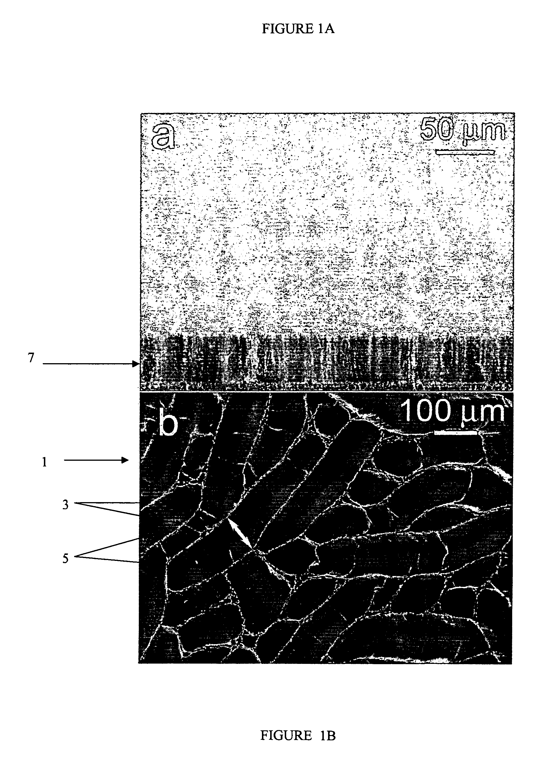
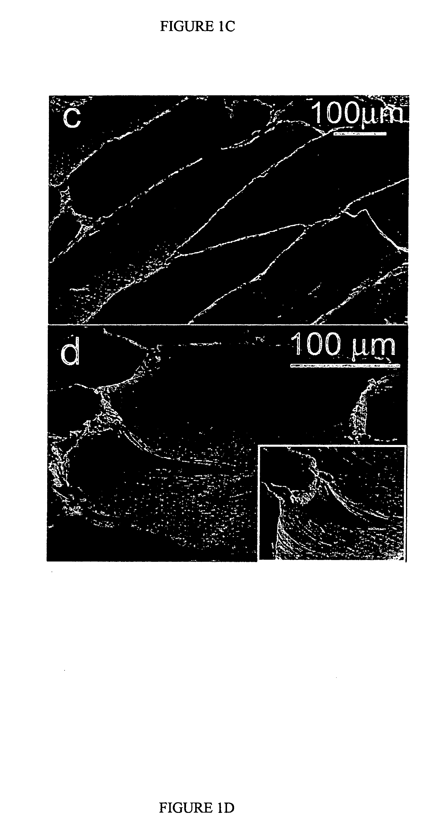
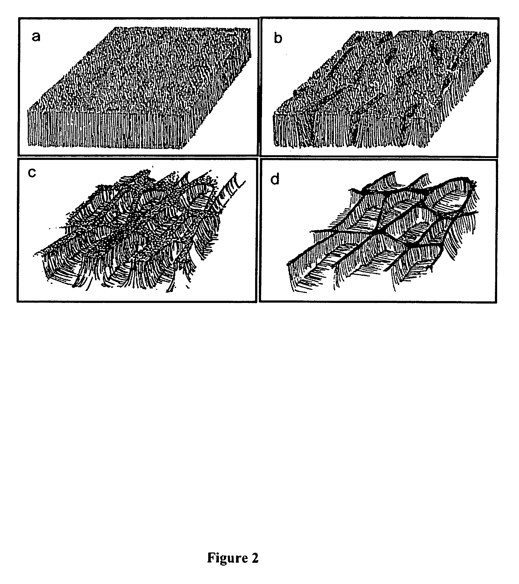
[0011] In a first preferred embodiment, the present inventors have discovered that the carbon nanotubes may be formed into a foam by evaporation of a liquid from nanotubes. As used herein, a nanotube foam comprises a material having a cellular structure. The carbon nanotubes self assemble into the cellular structure pattern due the step of evaporating the liquid from the nanotubes.

[0012] Preferably but not necessarily, the carbon nanotube foam comprises of a cellular film containing an open cellular structure. In other words, the foam preferably comprises a “two-dimensional”, open celled foam film whose height or thickness in the third dimension is less than, but determined by the height of the initially formed carbon nanotubes. Of course, if desired, plural “two-dimensional” foams may be stacked on top of each other to form a “three-dimensional” structure.

[0013]FIGS. 1B-1D show exemplary formation of cellular patterns by the evaporation of liquids from substantially vertically al...


PUM

PropertyMeasurementUnit
widthaaaaaaaaaa
lengthaaaaaaaaaa
widthaaaaaaaaaa

Abstract

A method of making a carbon nanotube structure includes providing an array of substantially aligned carbon nanotubes, wetting the array with a liquid, and evaporating the liquid to form the carbon nanotube structure having a pattern in the carbon nanotube array. The structure is preferably a carbon nanotube foam.

Description

STATEMENT REGARDING FEDERALLY SPONSORED RESEARCH & DEVELOPMENT [0001] The U.S. government may have certain rights in this invention pursuant to grant number DMR-0408745 from the National Science Foundation and the NSEC.BACKGROUND OF THE INVENTION [0002] The present invention relates generally to the field of carbon nanotubes and specifically to carbon nanotube foams. [0003] Multi-walled carbon nanotubes (MWNTs) have been produced by several different methods, including chemical vapor deposition (CVD) and laser ablation. These nanotubes are either grown as a layer of aligned nanotubes or as intertwined, randomly oriented bundles of nanotubes. [0004] Carbon nanotubes have many potential applications due to their mechanical, electrical and electronic properties. However, the difficulty in assembling the nanotubes into desired complex architectures and patterns hinder some of these applications. SUMMARY OF THE INVENTION [0005] One embodiment of the invention relates to a composition of ...

Claims


Application Information

Patent Timeline
Patent Type & Authority Applications(United States)
IPC IPC(8): D01F9/12
CPCA61L27/08Y10T428/12424A61L27/56A61L2400/12B01D39/2055B01D67/0072B01D67/0088B01D67/0093B01D71/021B01D2239/10B01D2239/1216B01D2239/1291B60R13/02B60R13/08B82Y30/00B82Y40/00C01B31/0253D01F9/127H01M4/583H01M4/96Y02E60/50B01D2323/24B01D2325/08B01D2325/24Y10S977/742A61L27/422C01B32/168Y02E60/10
Inventor AJAYAN, PULICKELCARRILLO, ALVAROCHAKRAPANI, NIRUPAMAKANE, RAVINDRA S.WEI, BINGQING
Owner RENESSELAER POLYTECHNIC INST
Why Eureka
Try Eureka