Flow direction control mechanism

a flow direction and control mechanism technology, applied in the direction of electrical apparatus casings/cabinets/drawers, domestic cooling apparatus, cooling/ventilation/heating modifications, etc., can solve the problems of increasing fabrication costs and structural complexity, reducing the heat dissipation reducing the efficiency of electronic devices, etc., to achieve the effect of increasing the fabrication cost of flow direction control mechanisms

Inactive Publication Date: 2006-04-06
TSAI I HSUAN +3
View PDF9 Cites 35 Cited by
  • Summary
  • Abstract
  • Description
  • Claims
  • Application Information

AI Technical Summary

Benefits of technology

[0013] Another objective of the invention is to provide a flow direction control mechanism for controlling and preventing reverse airflow and for improving convection and heat dissipating efficiency in a passage of an electronic device.
[0014] In order to achieve the foregoing and other objectives, the present invention provides a flow direction control mechanism including a rotatable means mounted in a passage of an electronic device, wherein the rotatable means moves to an open position by means of a force generated from airflow flowing through the passage in operation of a heat dissipating device in the electronic device, and the rotatable means returns to a close position without requiring an external force. Further, a restricting means or restrictor may be mounted close to the rotatable means for restricting movement of the rotatable means between the open position and the close position, so as to control a flowing direction of airflow in the passage and prevent reverse airflow to thereby improve convection and heat dissipating efficiency.
[0018] Moreover, size, number and shape of the rotatable means and restrictor may be flexibly designed according to the structure of the passage. And, a plurality of the flow direction control mechanisms may be integrated as a module type to be detachably mounted at suitable positions in the passage of the electronic device, so as to desirably achieve airflow control improvement without significantly increasing fabrication costs of the flow direction control mechanism.

Problems solved by technology

Besides, heat dissipation plays an important role in system stability of CPUs in computers or other electronic devices; therefore, one main problem to be solved is to enhance heat dissipating efficiency in order to improve system performance.
Besides the reverse airflow, it also seriously affects exhaust of inner air in the passage or even affects operation of the first fan 101, making heat dissipating efficiency of the electronic device undesirably reduced; this problem would be more sever in an electronic device with an advanced CPU that is in high demand of heat dissipation.
However, provision of the compensation mechanism would increases fabrication costs and structural complexity; as it needs to take a period of time for the compensation mechanism to detect and react to malfunctioning of the fan, the electronic device may be broken down due to high temperature before an action or response is made by the compensation mechanism.
Moreover, as the fans are directly connected with air inlets or air outlets, reverse airflow occurs in a breakdown of the malfunctioning fan and also affects operation of other normally-functioning fans by which efficiency of convection or heat dissipation is significantly reduced, thus increasing load of the compensation mechanism and making the compensation mechanism easily damaged.

Method used


Image

  • Flow direction control mechanism
  • Flow direction control mechanism
  • Flow direction control mechanism

Examples


first preferred embodiment

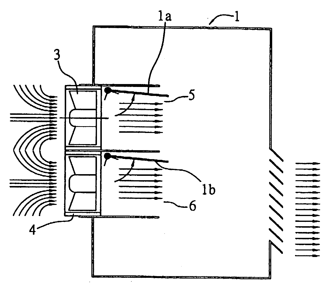
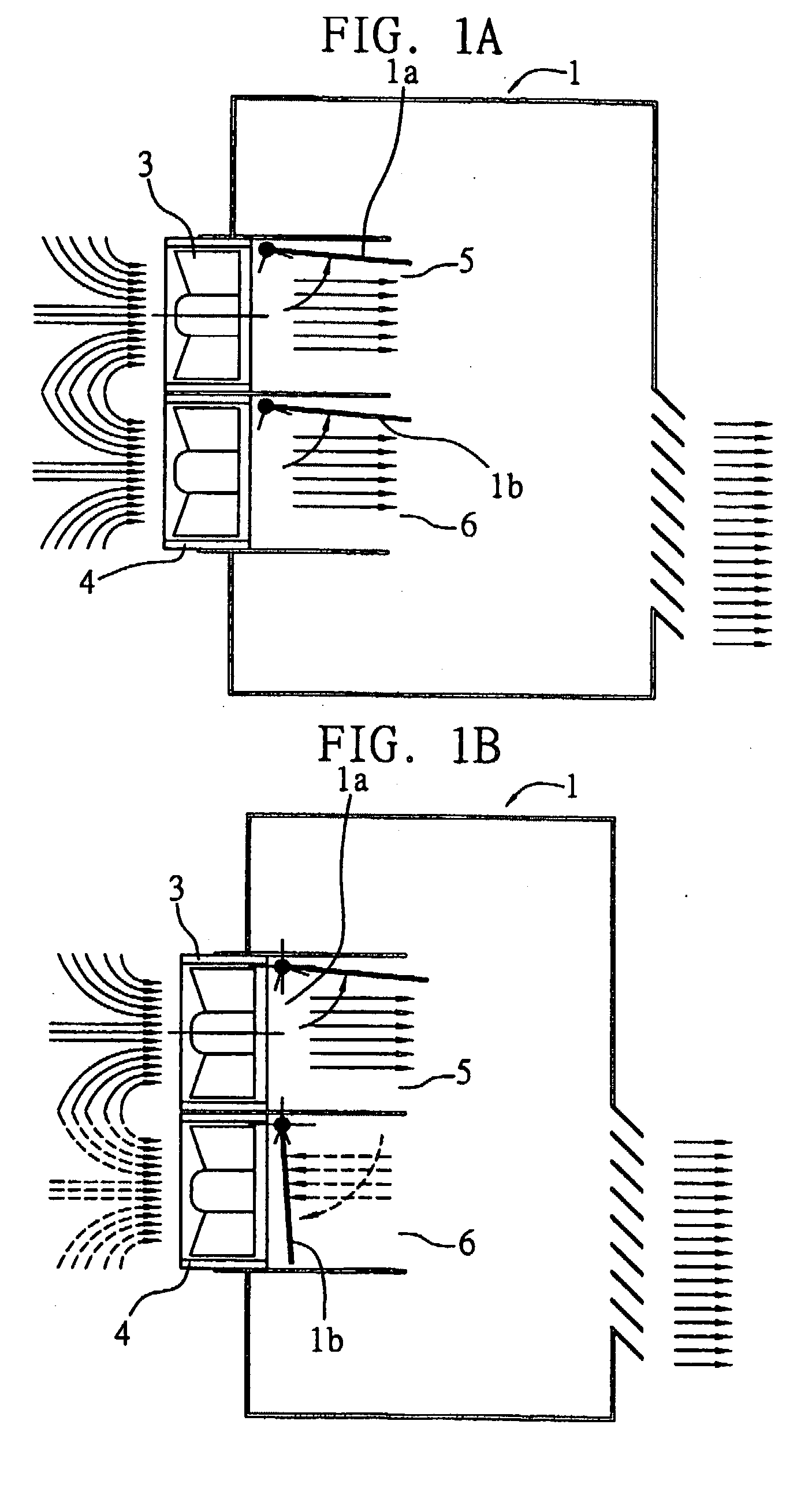
[0037]FIGS. 1A and 1B illustrate a flow direction control mechanism according to a first embodiment of the invention. A pair of these flow direction control mechanisms 1 having rotatable means 1a, 1b are disposed at air inlets 5, 6 of a passage of an electronic device and at inner positions with respect to heat dissipating devices 3, 4.

[0038] The rotatable means 1a, 1b can be rotatably mounted to a top, side or bottom wall of the passage of the electronic device, and spaced apart from the heat dissipating devices 3, 4 by a proper distance to avoid undesirably interference.

[0039] The heat dissipating devices 3, 4 are each mounted in the passage of the electronic device, and operate to produce airflow for directing air in the passage through air inlets 5, 6 toward outside for exhaust. The heat dissipating devices 3, 4 can be heat dissipating fans such as axial flow fans or centrifugal fans.

[0040] As shown in FIG. 1A, when the heat dissipating devices 3, 4 operate properly and respe...

second preferred embodiment

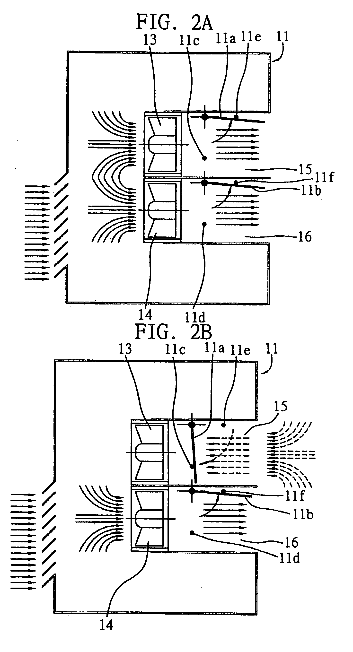
[0044]FIGS. 2A to 2D illustrate a flow direction control mechanism according to a second embodiment of the invention. A pair of these flow direction control mechanisms 11 are disposed at air outlets 15, 16 of the passage of an electronic device and at outer positions with respect to heat dissipating devices 13, 14. The flow direction control mechanisms 11 are formed with rotatable means 11a, 11b and restrictors 11c, 11d, 11e, 11f, wherein the restrictors 11c, 11d, 11e, 11f are each a protrusion formed on an inner side wall of the passage. The rotatable means 11a, 11b of the second embodiment are structured and have the same functions as those in the first embodiment; therefore, no further description thereto is to be here repeated. The second embodiment only differs from the first embodiment in that the rotatable means 11a, 11b are located near the air outlets 15, 16 of the passage and the restrictors 11c, 11d, 11e, 11f are provided.

[0045] As shown in FIG. 2A, when the heat dissipa...

third preferred embodiment

[0049]FIGS. 3A and 3B illustrate a flow direction control mechanism according to a third embodiment of the invention. This flow direction control mechanism 7 has the structure similar to that of the first embodiment with the only difference in that the flow direction control mechanisms 7 are installed at outside position rather than inner positions (first embodiment) with respect to heat dissipating devices 9, 10.


PUM


Abstract

A flow direction control mechanism is provided, which includes at least a rotatable means provided in a passage of an electronic system or apparatus. The rotatable means moves to an open position by means of a force generated from fluids flowing through the passage and returns to a close position in the absence of the force. Further, a restrictor is disposed adjacent to the rotatable means for restricting movement of the rotatable means between the open position and the close position.

Description

FIELD OF THE INVENTION [0001] The present invention relates to flow direction control mechanisms, and more particularly, to a flow direction control mechanism installed in a passage of a system or a device for controlling the airflow direction and eliminating the occurrence of reverse flow or air turbulence. BACKGROUND [0002] OF THE INVENTION [0003] Modern electronic devices such as computers and mobile phones are developed with advancement of technology and have central process units (CPUs) thereof to be more efficient in arithmetic calculation, thereby producing more heat during operation of the electronic devices and making heat dissipation or temperature control more significantly concerned for the electronic devices. For example, it is critical to prevent electromigration effect that is induced by temperature rising above a threshold and causes a malfunction or breakdown of the electronic devices. Besides, heat dissipation plays an important role in system stability of CPUs in ...

Claims


Application Information

Patent Timeline
Patent Type & Authority Applications(United States)
IPC IPC(8): H05K5/00F25D1/00H05K7/20
CPCH05K7/2019
Inventor TSAI, I-HSUANWEN, CHAO-WUHUANG, WEN-SHICHUANG, TE-TSAI
Owner TSAI I HSUAN
Why Eureka
Try Eureka