Magnetic resonance imaging system and method

a magnetic resonance imaging and magnetic resonance technology, applied in the field of magnetic resonance imaging systems, can solve the problems of inefficiency of pulse sequences and other problems

Inactive Publication Date: 2006-04-06
GENERAL ELECTRIC CO
View PDF5 Cites 9 Cited by
  • Summary
  • Abstract
  • Description
  • Claims
  • Application Information

AI Technical Summary

Problems solved by technology

Such pulse sequences are also not very efficient because FSE signals can only be read out at or near the T1 null thus making the useful imaging window less than a hundred millisecond out of each heart beat.

Method used


Image

  • Magnetic resonance imaging system and method
  • Magnetic resonance imaging system and method
  • Magnetic resonance imaging system and method

Examples


Embodiment Construction

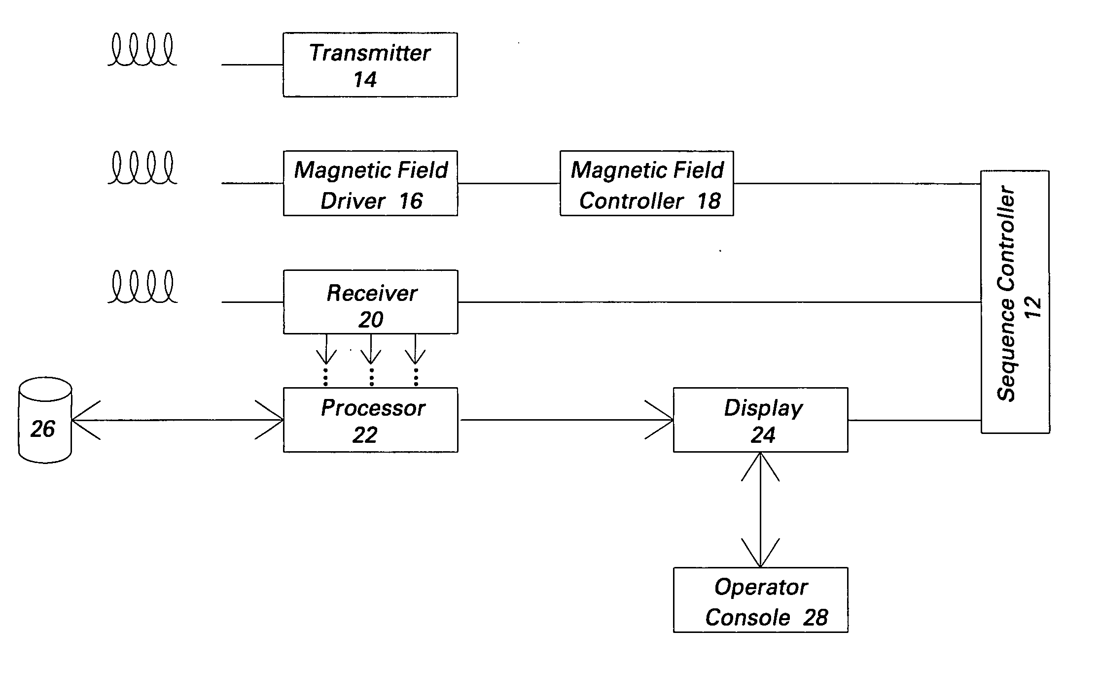
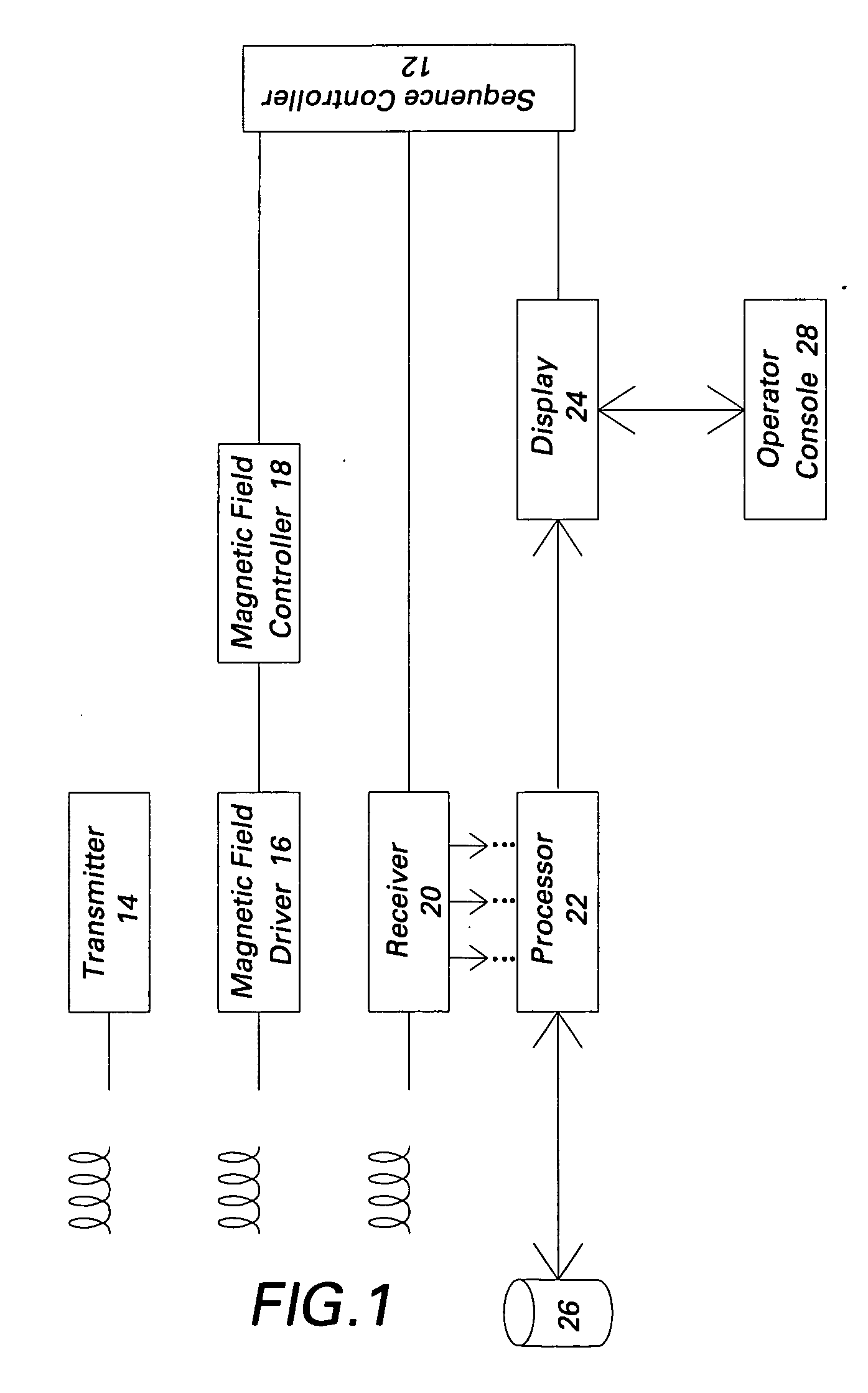
[0015]FIG. 1 is a block diagram of an exemplary magnetic resonance imaging (MRI) system for which embodiments of the present invention are applicable. The MR system could be, for example, a GE-Signa MR scanner available from GE Healthcare, which is adapted to perform the method of the present invention, although other systems could be used also.

[0016] As used herein, “adapted to”, “configured” and the like refer to devices in a system to allow the elements of the system to cooperate to provide a described effect; these terms also refer to operation capabilities of electrical or optical elements such as analog or digital computers or application specific devices (such as an application specific integrated circuit (ASIC)), amplifiers or the like that are programmed to provide an output in response to given input signals, and to mechanical devices for optically or electrically coupling components together

[0017] The MRI system 10 comprises a sequence controller 12 for controlling vari...


PUM


Abstract

A magnetic resonance imaging (MRI) system using a double inversion recovery (DIR) imaging pulse sequence for acquiring black-blood images for obtaining a first level of nulling of a blood signal from acquired imaging slices is provided. The MRI system comprises an image processor configured changing a respective time order of the imaging slices at a selected point or points during the pulse sequence to obtain a second level of nulling of the residual blood signal from the imaging slices.

Description

BACKGROUND [0001] The invention relates generally to magnetic resonance imaging (MRI) systems and more specifically to a method and system for acquiring images in MRI systems. [0002] MRI pulse sequences such as the double-inversion-recovery fast-spin-echo (DIRFSE) pulse sequences have the useful property of nulling the signals from blood that is flowing through an imaging plane. The resulting black-blood images allow better visualization of vessel walls including any plaque components, myocardium, and the like, because of reduced competition with bright blood signals from neighboring pixels. [0003] Typically, the DIRFSE pulse sequence employs, after an electrocardiogram (ECG) trigger, a nonselective inversion pulse and, at nearly the same time, a slice-selective inversion of a slice that incorporates the imaging slice. After a delay period (typically several hundred milliseconds) depending on the T1 of blood, a fast spin echo (FSE) imaging sequence is played out. [0004] The combinat...

Claims


Application Information

Patent Timeline
Patent Type & Authority Applications(United States)
IPC IPC(8): A61B5/05
CPCG01R33/563
Inventor HARDY, CHRISTOPHER JUDSONDIXON, WILLIAM THOMASZONG, XULI
Owner GENERAL ELECTRIC CO
Why Eureka
Try Eureka