Supercharge Your Innovation With Domain-Expert AI Agents!

Device and method for expansion forming

a technology of expansion forming and equipment, which is applied in the direction of metal-working apparatus, manufacturing tools, shaping tools, etc., can solve the problems of large opening force generation, difficult to keep downward deflection in large press platens within the desired limits, and financial doubt in building plants in conventional manner, etc., to achieve easy replacement, increase the volume of the pressure cell, and reduce the effect of volum

Inactive Publication Date: 2006-04-13
QUINTUS TECH
View PDF11 Cites 3 Cited by
  • Summary
  • Abstract
  • Description
  • Claims
  • Application Information

AI Technical Summary

Benefits of technology

[0010] Another object of the present invention is to provide a device and a method which allow inexpensive expansion forming of large articles.
[0036] Unlike the expanding and stretching motion of a single diaphragm, a plate according to the invention is preferably movable as a whole. The plate can conveniently be caused to carry out a translatory movement, i.e. a movement which means that all the points of the plate are moved in parallel the same distance, i.e. without turning the plate. This parallel movement can be used to increase the volume of the pressure cell in view of the forming operation (e.g. by lowering the plate if it is adapted to abut against the upper side of the tool) and to reduce the volume (e.g. by raising the plate). This movability can be adjustable, not only by means of a liquid, such as oil, but also by means of vacuum suction or a spring assembly or any other suitable means. Thus, when the expansion forming has been completed, the plate is removed from the tool, for example by evacuating the liquid from the pressure cell and causing the plate to spring back or be sucked back into position, whereby the tool can be easily accessed and removed from the press.

Problems solved by technology

In the case of large blanks having large areas of exposure and high forming pressures, large opening forces are generated.
It is difficult to keep the downward deflections in large press platens within the desired limits.
When great forces are involved (more than 10,000 tons, i.e. about 100 MN), building plants in conventional manner becomes financially doubtful.
Although such an arrangement has certain advantages compared with conventional press platens, it is still not enough to prevent deformations of the tool or avoid unevenly distributed loads at very high pressures.
Consequently, more rigid tools would be required also in this case, which is a problem because it means that a thicker tool is needed to obtain the desired rigidity.

Method used


Image

  • Device and method for expansion forming
  • Device and method for expansion forming
  • Device and method for expansion forming

Examples


Embodiment Construction

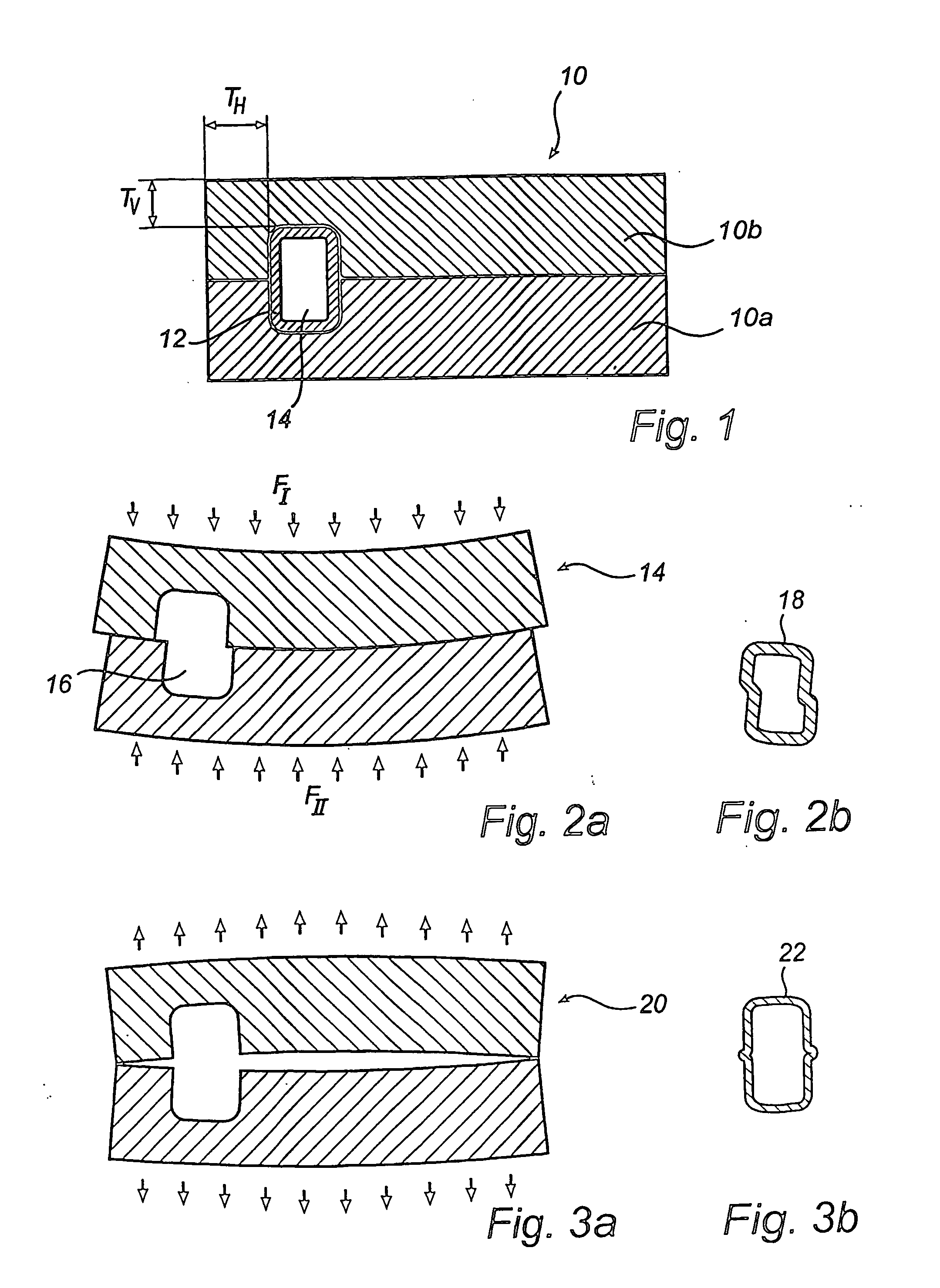
[0053]FIG. 1 is a cross-sectional view of an expansion forming tool 10 with an initial blank 12 or a workpiece arranged in the cavity. The tool 10 consists of two tool halves, namely a lower half 10a and an upper half 10b. The tool halves have hollows or recesses which, when the halves are joined together, form at least one cavity 14 (for the sake of clarity only one cavity is shown). The wall thickness of the tool 10 from the cavity to the exterior is indicated in the figure by TV for the vertical thickness and TH for the horizontal thickness. Depending on the thickness and rigidity of these walls and the internal forming pressure, it may be appropriate to pressure-compensate said walls by means of an external application of force. If pressure compensation is not provided or provided in an incorrect manner, deformations may arise, as illustrated in FIGS. 2a-b and 3a-b.

[0054]FIG. 2 is a cross-sectional view of an expansion forming tool 14, which is exposed to an uneven load. The de...


PUM

PropertyMeasurementUnit
pressuresaaaaaaaaaa
forcesaaaaaaaaaa
pressureaaaaaaaaaa

Abstract

The present invention relates to a method and a device for expansion forming of an article. According to at least one aspect of the invention, an expansion forming tool is pressure-compensated from two sides, pressure differences on each side being equalized by means of a pressure transmitter, which is applicable to the tool.

Description

[0001] The present application claims priority of U.S. Provisional Application No. US 60 / 380,424 and Swedish Applications Nos SE 0201415-7 and SE 0201470-2.TECHNICAL FIELD [0002] The present invention relates to a device and a method for expansion forming of an article using a blank adapted to be formed into said article in the cavity of an expansion forming tool. BACKGROUND ART [0003] Tubular articles are used in different industrial applications. In the automotive industry, the cars manufactured may, for example, be provided with tubular side beams and also with bodies of so-called space frame construction. It would seem convenient to manufacture these types of tubular articles by means of expansion forming. [0004] In expansion forming, an expansion forming tool is used. The tool comprises a cavity having the shape intended for a finished article. The tool usually comprises two milled-out tool halves made of steel, the recess in the tool halves forming the cavity. An initial blank...

Claims


Application Information

Patent Timeline
Patent Type & Authority Applications(United States)
IPC IPC(8): B21D26/02B21D26/039
CPCB21D26/039B21D26/047B21D37/12
Inventor HELLGREN, KEIJO
Owner QUINTUS TECH
Features
  • R&D
  • Intellectual Property
  • Life Sciences
  • Materials
  • Tech Scout
  • Unparalleled Data Quality
  • Higher Quality Content
  • 60% Fewer Hallucinations
Learn More