Integratable polarization rotator

a rotator and polarization technology, applied in the field of optical communication system, can solve the problems of preventing the normal operation of the optical system, affecting the operation of the laser,

Inactive Publication Date: 2006-04-13
INTEL CORP
View PDF3 Cites 5 Cited by
  • Summary
  • Abstract
  • Description
  • Claims
  • Application Information

AI Technical Summary

Problems solved by technology

Back reflections may disturb the operation of a l...

Method used


Image

  • Integratable polarization rotator
  • Integratable polarization rotator
  • Integratable polarization rotator

Examples


Embodiment Construction

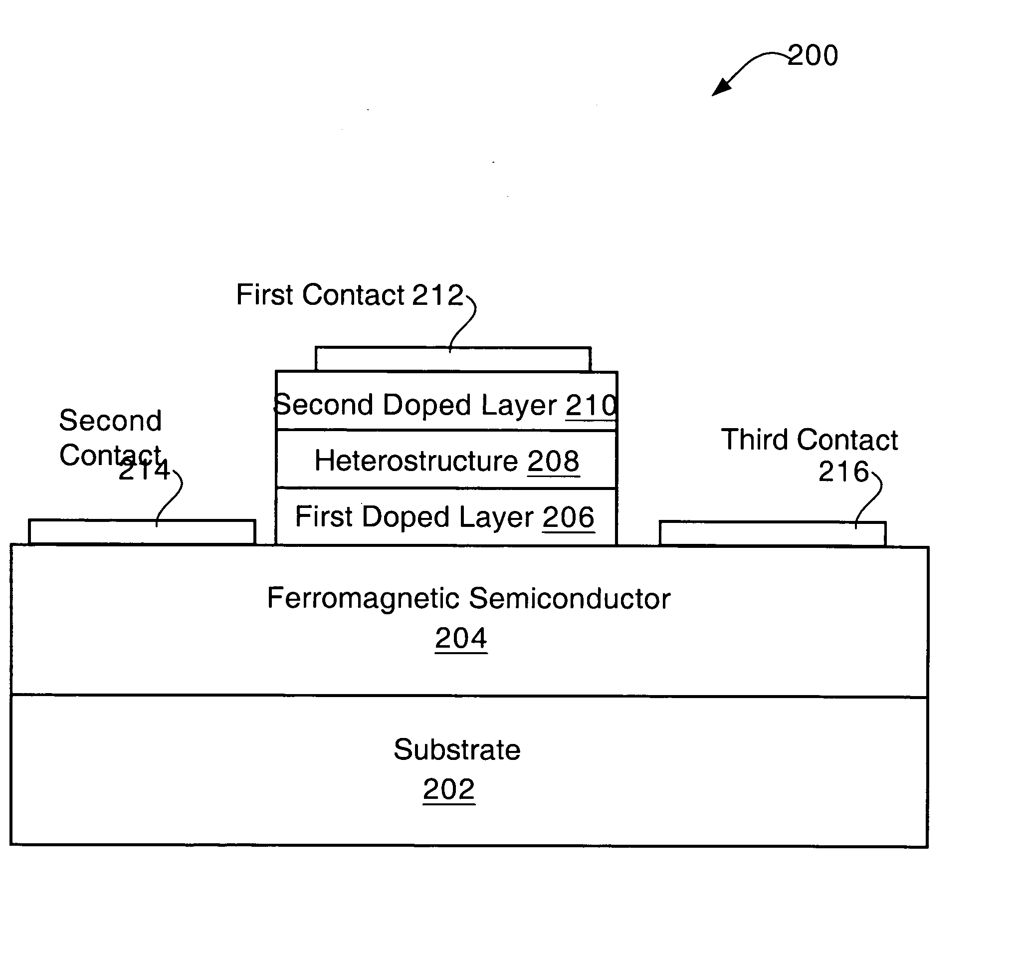
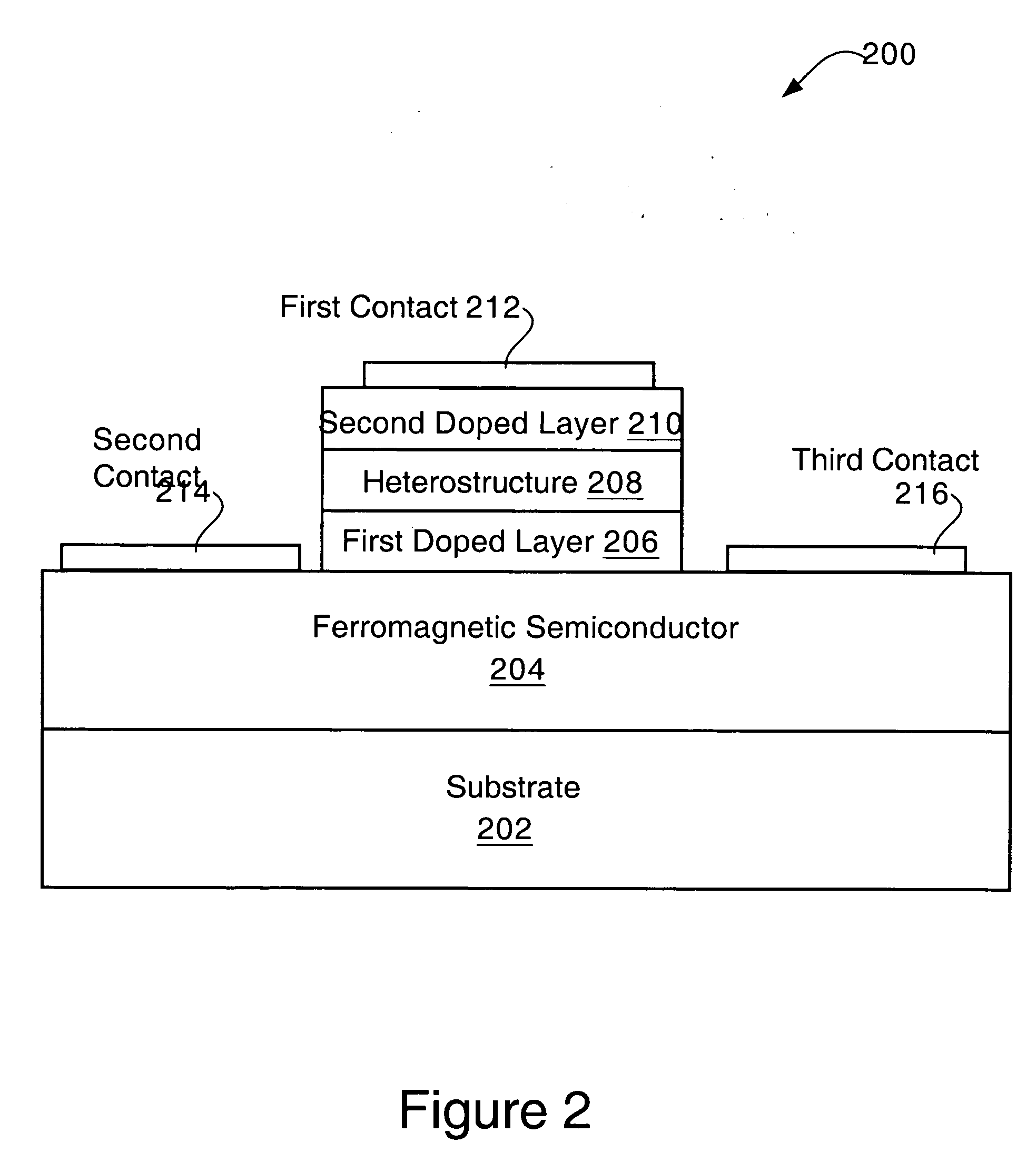
[0009] In various embodiments, an apparatus and method relating to the formation of a device integrated in a substrate are described. In the following description, various embodiments will be described. However, one skilled in the relevant art will recognize that the various embodiments may be practiced without one or more of the specific details, or with other methods, materials, or components. In other instances, well-known structures, materials, or operations are not shown or described in detail to avoid obscuring aspects of various embodiments of the invention. Similarly, for purposes of explanation, specific numbers, materials, and configurations are set forth in order to provide a thorough understanding of the invention. Nevertheless, the invention may be practiced without specific details. Furthermore, it is understood that the various embodiments shown in the figures are illustrative representations and are not necessarily drawn to scale.

[0010] Reference throughout this spe...


PUM


Abstract

Embodiments of the invention provide a polarization rotator. The polarization rotator may be integrated with a waveguide on a substrate, and may include a ferromagnetic semiconductor layer on the substrate, a first doped layer on the ferromagnetic semiconductor layer, and a second doped layer on the first doped layer.

Description

BACKGROUND Background of the Invention [0001]FIG. 1 is a schematic diagram illustrating an optical communications system 100 that converts an electrical signal 102 carried by a conductor such as a metal wire to an optical signal 108 carried by a transmissive medium such as a glass fiber. An optical source 104, such as a laser, may receive the electrical signal 102 and produce and convert it to an optical signal 108. The optical signal 108 may be carried by a transmissive medium such as an optical fiber to a destination, or may be transmitted through air or a vacuum. An isolator 106 may be used to prevent back reflections. Back reflections may disturb the operation of a laser and prevent normal operation of an optical system. The isolator 106 may include a polarization rotator. BRIEF DESCRIPTION OF THE DRAWINGS [0002]FIG. 1 is a schematic diagram illustrating an optical system. [0003]FIG. 2 is a side cross sectional view that illustrates a generalized integrated polarization rotator....

Claims


Application Information

Patent Timeline
IPC IPC(8): H01L29/76H01L21/338
CPCG02B6/12004G02B6/26G02B6/2746G02F1/025H01F1/405H01F1/402H01F1/404H01F10/193G02F1/0955
Inventor SALIB, MICHAEL S.NIKONOV, DMITRI
Owner INTEL CORP
Why Eureka
Try Eureka