Magnetic field-producing device

a generator and magnetic field technology, applied in the direction of permanent magnets, magnetic bodies, instruments, etc., can solve the problems of ineffective magnetic circuit configuration, inability to generate a very large magnetic field uniformity space capable of covering the entire body from the head to the feet, and inability to provide effective magnetic field configuration. achieve high uniform magnetic field, maintain the magnetic field uniformity and strength, and high magnetic field uniformity

Inactive Publication Date: 2006-04-13
SUMITOMO SPECIAL METAL CO LTD
View PDF12 Cites 45 Cited by
  • Summary
  • Abstract
  • Description
  • Claims
  • Application Information

AI Technical Summary

Benefits of technology

[0007] The magnetic field generator according to the present invention is a permanent magnet type. Therefore, unlike those which use electric magnets, there is no need for operations to switch electric currents. By adjusting the magnetic fields generated in the plurality of magnetic field uniformity spaces in advance, a highly uniform magnetic field is obtained at a plurality of places in a single magnetic field generator, and it is possible to sustain the magnetic field uniformity and strength. Therefore, even when the magnetic field uniformity spaces generate different magnetic fields from each other, highly accurate magnetic field distribution is obtainable. Thus, it is possible to obtain e.g. an apparatus which serves as both high-quality MRI apparatus and ESR imaging apparatus, and an MRI apparatus which allows simultaneous MRI image taking of two or more parts.
[0008] Preferably, the magnetic field generator includes: a pair of yokes faced to each other with a gap in between; and at least two pairs of magnetic poles. The poles in each pair are faced with each other between the pair of yokes, and the magnetic field uniformity space is formed between each pair of the magnetic poles. In this case, a plurality of pairs of magnetic poles are provided between a pair of yokes, and it is possible to form a plurality of magnetic field uniformity spaces between one pair of yokes. Therefore, magnetic efficiency can be improved over a case where a plurality of magnetic field generators are placed side by side, making possible to reduce the size of the apparatus.
[0009] Further preferably, the magnetic pole includes a pole piece. In this case, it is possible to improve uniformity of the magnetic field uniformity space.
[0011] Preferably, at least a pair of the magnetic poles includes a permanent magnet group. In this case, it is possible to build a magnetic circuit which passes through such a pair of magnetic poles and the other pair of magnetic poles. Therefore, even if the other pair of magnetic poles does not include permanent magnet groups, it is possible to form a magnetic field uniformity space between that pair of magnetic poles. Further, it becomes possible to reduce a total amount of permanent magnet used for the construction, and thereby to reduce the weight of magnetic field generator.
[0013] Further, preferably, two magnetic field uniformity spaces which are adjacent to each other have their magnetic field directions differing from each other by 180 degrees. In this case, it is possible to build a magnetic circuit without supporting yokes such as a back yoke. Therefore, it becomes possible to reduce the weight of the magnetic field generator. Further, it becomes possible to reduce psychological pressure on the examinee.
[0016] Further, preferably, electromagnetic shielding means is provided between two magnetic field uniformity spaces which are adjacent to each other. This eliminates interference by noises due to signal generation etc. in each of the magnetic field uniformity spaces, and improves the quality of obtained image. Further, it becomes possible to reduce the distance between mutually adjacent magnetic field uniformity spaces, which enables further size reduction of the entire apparatus.

Problems solved by technology

In addition, because of magnetic hysteresis which develops in magnetic components such as yokes when electric current is switched, it is difficult to increase magnetic field uniformity in both of the high magnetic field and the low magnetic field.
This has a practical reason that an MRI apparatus which can generate a very large magnetic field uniformity space capable of covering the entire body from the head to the feet would become too huge.
Simply placing two MRI apparatuses will not provide an effective magnetic circuit configuration while the entire apparatus would become impractically large.

Method used


Image

  • Magnetic field-producing device
  • Magnetic field-producing device
  • Magnetic field-producing device

Examples


Embodiment Construction

[0034] Hereinafter, an embodiment of the present invention will be described, with reference to the drawings.

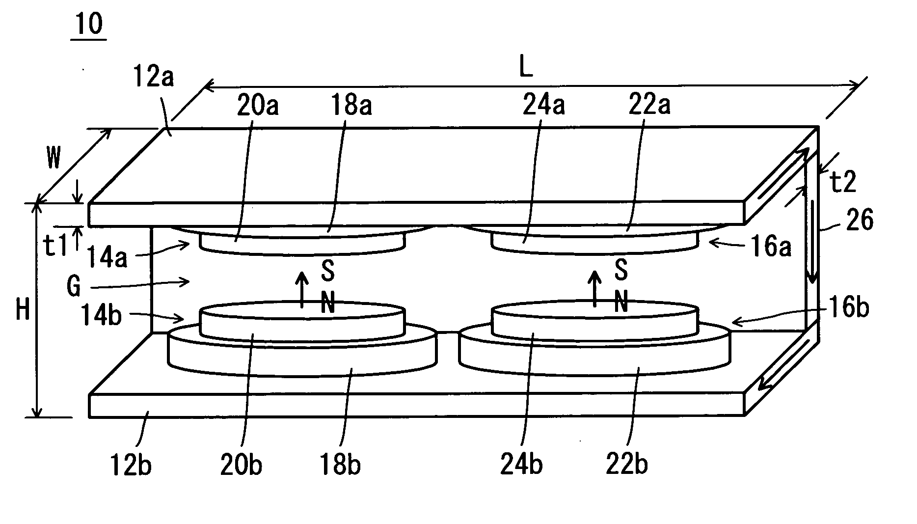
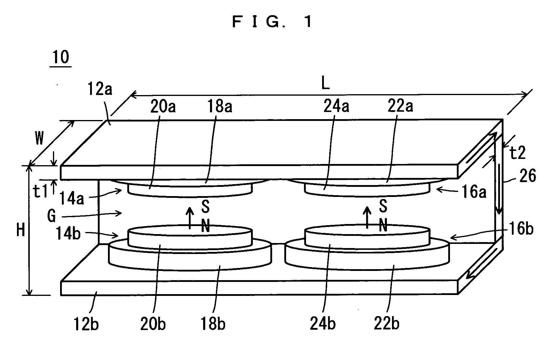
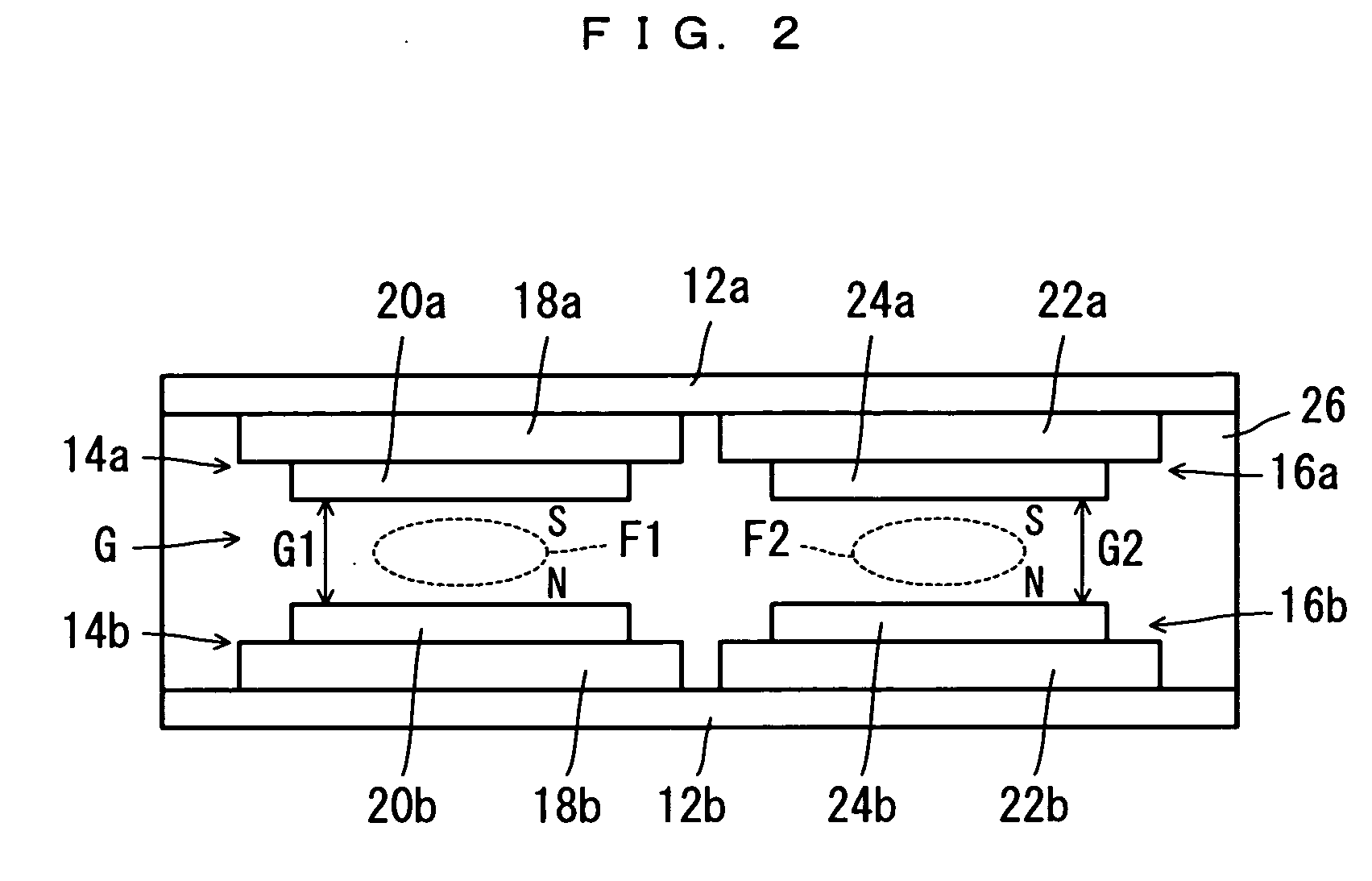
[0035] Referring to FIG. 1 and FIG. 2, a magnetic field generator 10 as an embodiment of the present invention is a permanent-magnet type magnetic field generator, and includes a pair of plate yokes 12a and 12b which are faced to each other to provide a gap G in between.

[0036] Between the pair of plate yokes 12a, 12b are two pairs of magnetic poles, i.e. a pair of magnetic poles 14a, 14b which are faced to each other, and another pair of magnetic poles 16a, 16b which are faced to each other.

[0037] The magnetic poles 14a, 14b include permanent magnet groups 18a, 18b respectively, which are disposed on the mutually opposed faces of the pair of plate yokes 12a, 12b. The permanent magnet groups 18a, 18b have their respective opposing faces provided with pole pieces 20a, 20b fixed thereon. Likewise, the magnetic poles 16a, 16b include permanent magnet groups 22a, 22b respective...


PUM

PropertyMeasurementUnit
magnetic fieldaaaaaaaaaa
thickness t2aaaaaaaaaa

Abstract

A magnetic field generator (10) which generates a high uniformity magnetic field at a plurality of locations is provided. The magnetic field generator (10) includes a pair of plate yokes (12a),(12b) which are faced to each other with a gap (G) in between. A pair of mutually opposed magnetic poles (14a),(14b), and another pair of mutually opposed magnetic poles (16a),(16b) are provided between the plate yokes (12a),(12b). The magnetic poles (14a),(14b) respectively include permanent magnet groups (18a),(18b) which are disposed on mutually opposed surfaces of the plate yokes (12a),(12b). Pole pieces (20a),(20b) are fixed to mutually opposed surfaces respectively of the permanent magnet groups (18a),(18b). The magnetic poles (16a),(16b) respectively include permanent magnet groups (22a),(22b) which are disposed on mutually opposed surfaces of the plate yokes (12a),(12b). Pole pieces (24a),(24b) are fixed to mutually opposed surfaces respectively of the permanent magnet groups (22a),(22b). Magnetic field uniformity spaces (F1),(F2) are formed between the pole pieces (20a),(20b) and between the pole pieces (24a),(24b) respectively.

Description

TECHNICAL FIELD [0001] The present invention relates to a magnetic field generator, and more specifically to a permanent magnet type magnetic field generator used in an MRI (Magnetic Resonance Imaging) apparatus, an ESR imaging (Electron Spin Resonance Imaging) apparatus or an apparatus which serves as both. BACKGROUND ART [0002] In order to take an MRI image and an ESR image simultaneously, two magnetic fields of different strengths are necessary. Generally, MRI requires a high magnetic field which has a strength not smaller than 0.2 T whereas ESR imaging requires a magnetic field whose strength is less than a half thereof (0.04 T for example). As an example of such an apparatus, JP-A 9-299347 proposes an apparatus which generates a magnetic field for an MRI and a magnetic field for an ESR imaging, with a single electric magnet. According to this method, the amount of electric current is varied in a single electric magnet, to switch between a resonance magnetic field strength for E...

Claims


Application Information

Patent Timeline
Patent Type & Authority Applications(United States)
IPC IPC(8): H01F7/02G01R33/383
CPCG01R33/383H01F7/0278
Inventor AOKI, MASAAKI
Owner SUMITOMO SPECIAL METAL CO LTD
Why Eureka
Try Eureka