Digital/analog converter, display device using the same, and display panel and driving method thereof
Active Publication Date: 2006-04-13
SAMSUNG DISPLAY CO LTD
View PDF18 Cites 14 Cited by
Summary
Abstract
Description
Claims
Application Information
AI Technical Summary
This helps you quickly interpret patents by identifying the three key elements:
Problems solved by technology
Method used
Benefits of technology
[0017] In another embodiment, a display panel includes a display unit including a plurality of pixels that display an image corresponding to applied data currents, and a grayscale current generator for converting a plurality of grayscale data into the data currents and applying the data currents to the plurality of pixels. In addition, the grayscale current generator divides the plurality of grayscale data into at least two grayscale ranges that include a first grayscale range,
Problems solved by technology
A pixel circuit according to a conventional voltage programming method has difficulties in expressing high-level grayscales due to deviations of threshold voltages VTH of TFTs and/or mobilities of carriers of the TFTs, the deviations being generated as a result of a non-uniform manufacturing process of the TFTs
Method used
Image
Click on the blue label to locate the original text in one second.
Reading with bidirectional positioning of images and text.
Examples
first embodiment
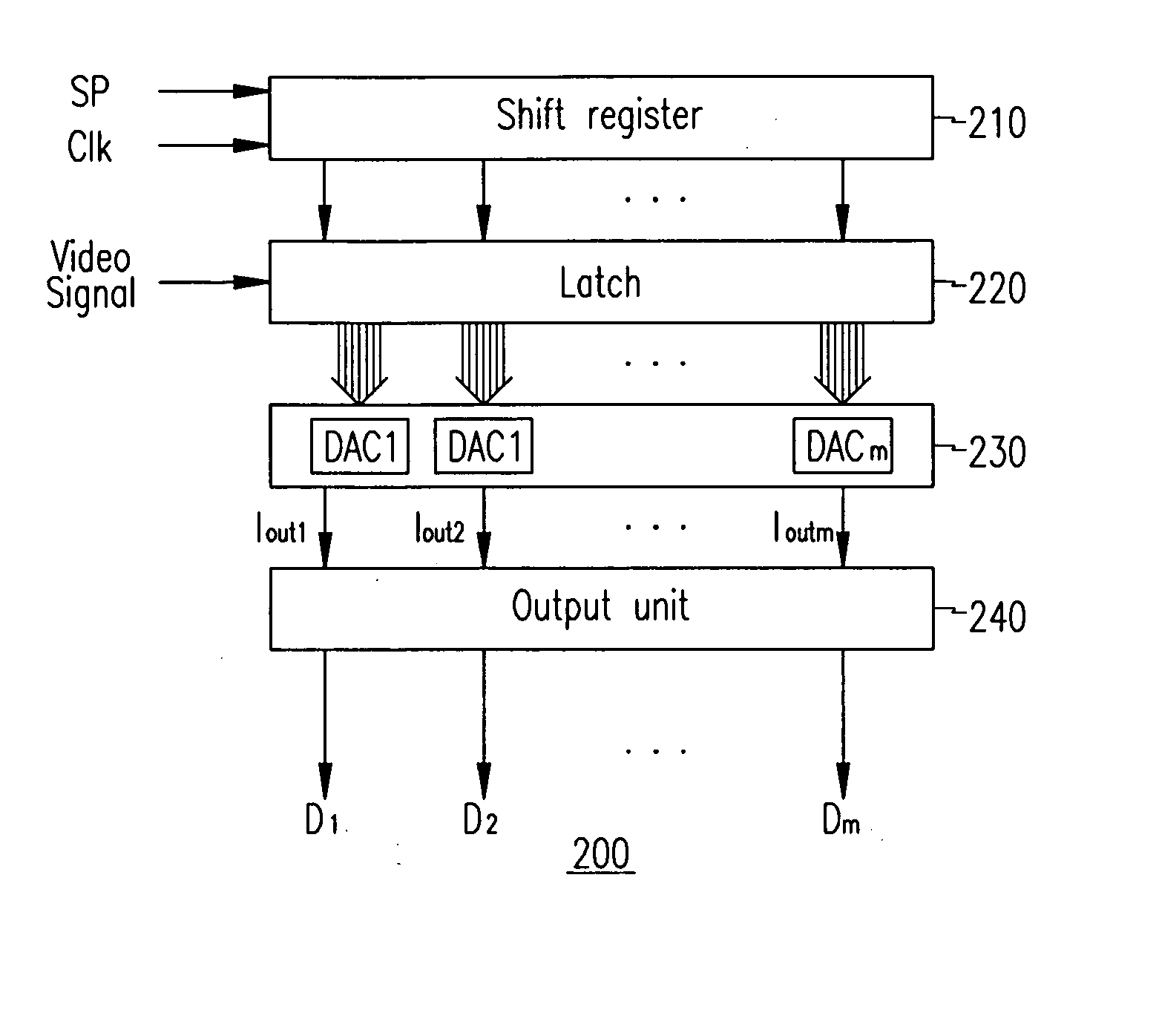
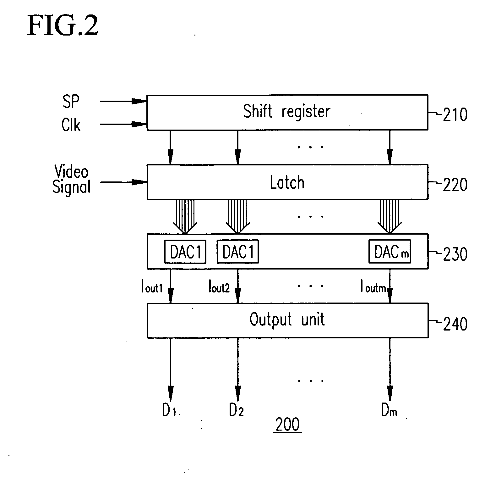
[0053] A grayscale current generator (e.g., the grayscale current generator 230) according to the present invention will now be described with reference to FIGS. 3, 4, and 5.
[0054] In the following descriptions, a video signal is described to be a 6-bit grayscale data, for better understanding and ease of description, but the present invention is not thereby limited.
[0055]FIG. 3 is a block diagram illustrating a D / A converter DACm of the grayscale current generator 230 according to the first embodiment of the present invention.
[0056]FIG. 4 illustrates a gamma curve according to the first embodiment of the present invention, and FIG. 5 exemplarily illustrates an output grayscale current corresponding to an input grayscale data of a second grayscale range.
[0057] As shown in FIG. 3, the D / A converter DACm includes a reference current output unit 231, a multiplexer 232, and a fine current output unit 233 according to the first embodiment of the present invention.
[0058] The reference...
second embodiment
[0087] A D / A converter (e.g., the D / A converter DACm) according to the present invention will now be described with reference to FIG. 7.
[0088]FIG. 7 illustrates the D / A converter (e.g., the D / A converter DACm) according to the second embodiment of the present invention.
[0089] The D / A converter (e.g., the D / A converter DACm) in the second embodiment is a current mirror D / A converter that uses a reference current in contrast with the D / A converter in the first embodiment of the present invention.
[0090] In more detail, the current mirror D / A converter of FIG. 7 includes a reference current output unit 231′, a fine current output unit 233′, a first multiplexer 234, and a second multiplexer 235 according to the second embodiment of the present invention.
[0091] The reference current output unit 231′ includes a current mirror circuit formed by transistors M11′, M12′, M31, and M32, and the first multiplexer 234.
[0092] The first multiplexer 234 selects a current that corresponds to a hig...
PUM
Abstract
A display device including a display unit including a plurality of data lines for transmitting data currents, a plurality of scan lines for transmitting scan signals, and a plurality of pixel areas defined by the data lines and the scan lines; a data driver for converting a plurality of grayscale data that include first data and second data into at least one of the data currents, and applying the at least one of the data currents to at least one of the data lines; and a scan driver for sequentially applying the scan signals to the plurality of scan lines, and wherein the data driver divides the plurality of grayscale data into at least two grayscale ranges including a first grayscale range, outputs a first current of the first grayscale range including at least one of the plurality of grayscale data by using the first data, and outputs a second current that corresponds to the second data in the first grayscale range.
Description
CROSS-REFERENCE TO RELATED APPLICATION [0001] This application claims priority to and the benefit of Korean Patent Application No. 10-2004-0080368, filed in the Korean Intellectual Property Office on Oct. 8, 2004, the entire content of which is incorporated herein by reference. FIELD OF THE INVENTION [0002] The present invention relates to a display device. More particularly, the present invention relates to an organic light emitting diode (OLED) display using a digital / analog converter, a display panel of the OLED display, and a driving method thereof. BACKGROUND OF THE INVENTION [0003] In general, an OLED display is a display device that electrically excites fluorescent organic material for emitting light and visualizes an image by voltage programming or current programming N×M organic light emitting pixels. [0004] An organic light emitting pixel (or diode) includes anode (indium tin oxide or ITO), organic thin film, and cathode (metal) layers. [0005] The organic thin film layer h...
Claims
Application Information
Patent Timeline
Application Date:The date an application was filed.
Publication Date:The date a patent or application was officially published.
First Publication Date:The earliest publication date of a patent with the same application number.
Issue Date:Publication date of the patent grant document.
PCT Entry Date:The Entry date of PCT National Phase.
Estimated Expiry Date:The statutory expiry date of a patent right according to the Patent Law, and it is the longest term of protection that the patent right can achieve without the termination of the patent right due to other reasons(Term extension factor has been taken into account ).
Invalid Date:Actual expiry date is based on effective date or publication date of legal transaction data of invalid patent.