Compensated inverse-time undervoltage load shedding systems

a load shedding system and load shedding technology, applied in non-electric variable control, process and machine control, instruments, etc., can solve the problems of heavy power system load that approaches or exceeds the limits of the power system, loss of a var generating source, and decrease of effective transformer turn ratios

Active Publication Date: 2006-04-13
SCHWEITZER ENGINEERING LABORATORIES
View PDF21 Cites 29 Cited by
  • Summary
  • Abstract
  • Description
  • Claims
  • Application Information

AI Technical Summary

Benefits of technology

[0013] Therefore, it is an aspect and object of this invention to provide a load shedding system which avoids one or more of the drawbacks of prior load shedding systems.

Problems solved by technology

Events that contribute to voltage instability of the power system may include, for example, a VAR (voltage-amperes reactive) generating source reaching its operability limits, the loss of a VAR generating source, a decrease of effective transformer turns ratios, a heavy power system loading that approaches or exceeds the power system's limits, and / or tripping of transmission lines and / or generators.
Instead, a sequence of events typically causes the voltage instability which may cascade into localized or widespread system voltage collapse.
Despite such first stage corrective actions, voltage instability may continue until power system voltage collapse and / or rotor angle instability (i.e., generator loss of synchronism).
While effective in some cases, utilizing definite time undervoltage relays for load shedding purposes has several drawbacks.
First, because each definite time undervoltage relay includes a timer having one predetermined time period, or interval, and one preselected voltage threshold, loads may be unnecessarily shed.
As a result, dynamic loads such as induction motors, load-tap changers and thermostatic loads demanding more reactive power from the system are not necessarily shed before static loads demanding less reactive power from the system.
As a result, the load shedding time delay can vary.
Thus, as the power system voltage measured by the relay decreases so does the load shedding time delay.
Although less likely to unnecessarily shed a load than the definite time undervoltage relay, the inverse time undervoltage relay may still unnecessarily shed a load if, for example, power system recovery to nominal operating voltage is slow.

Method used


Image

  • Compensated inverse-time undervoltage load shedding systems
  • Compensated inverse-time undervoltage load shedding systems
  • Compensated inverse-time undervoltage load shedding systems

Examples


Embodiment Construction

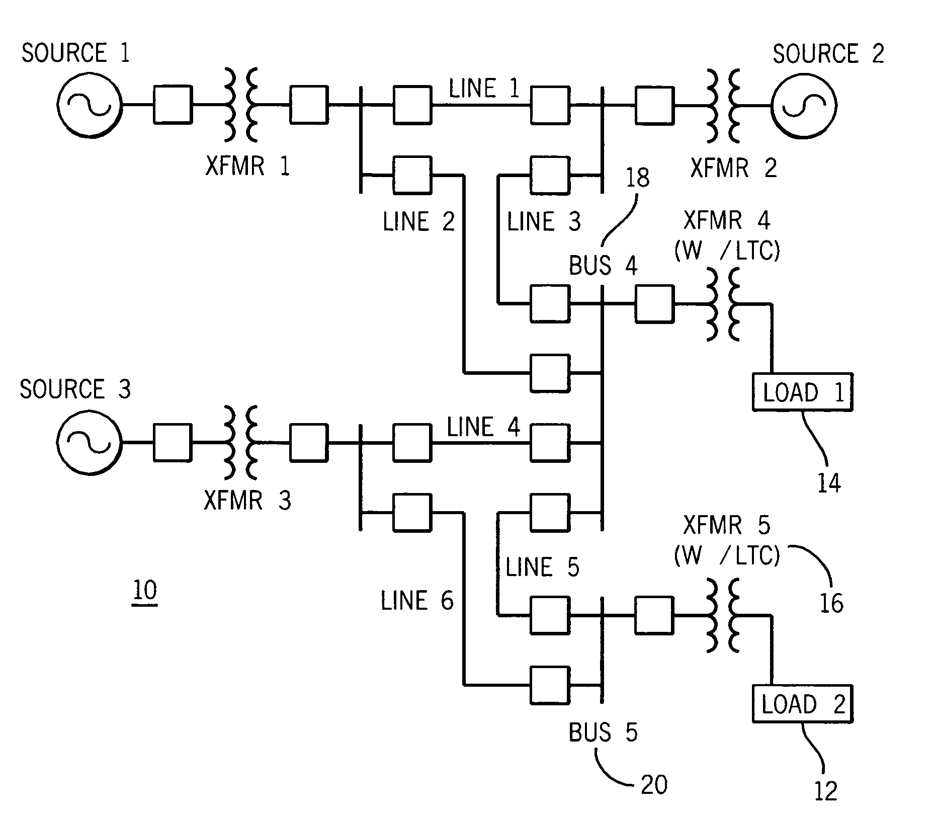
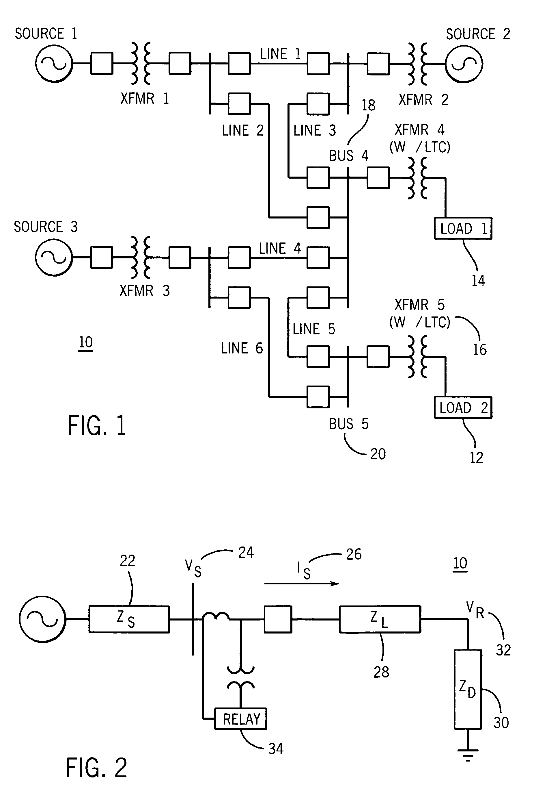
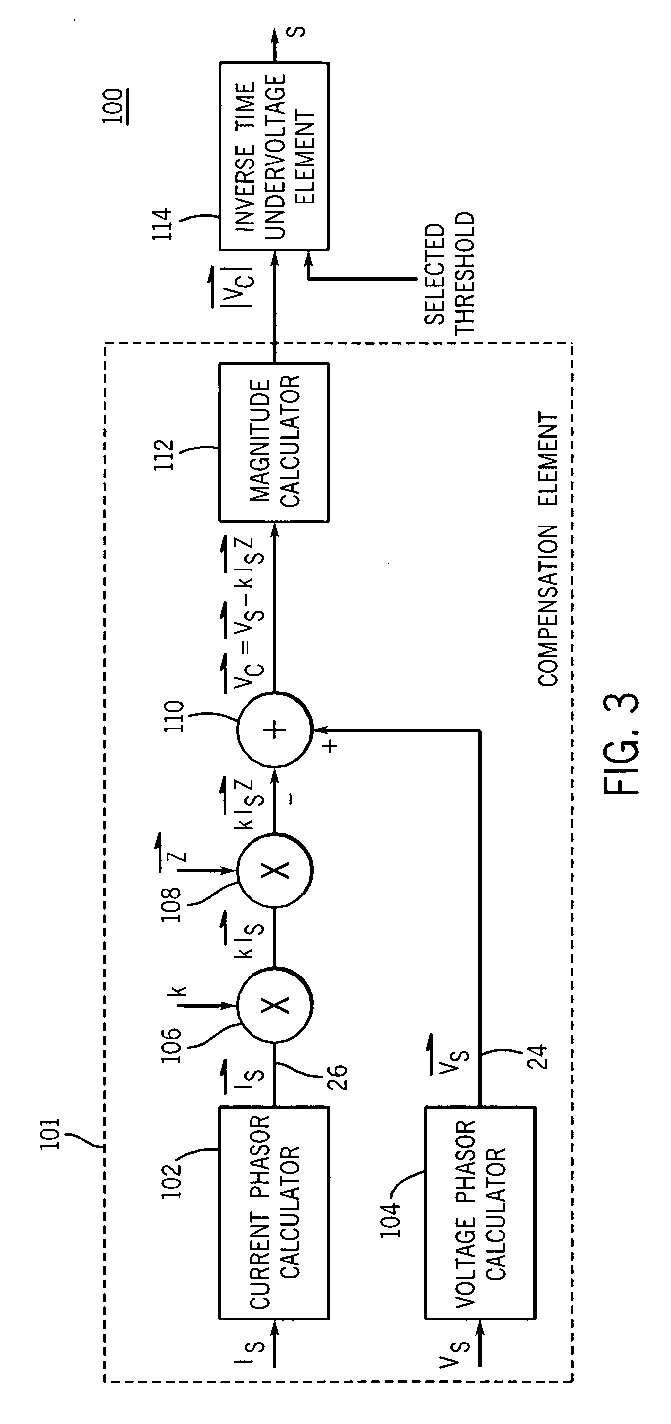
[0025] The multiple embodiments of this invention relate to undervoltage load shedding systems including a compensation element and an inverse-time undervoltage element utilized in an electric power system control or protective device for coordinated, system-wide load shedding. Generally, system control or protective devices are used for protecting, monitoring, controlling, metering and / or automating electric power systems and associated transmission lines. These system control or protective devices may include protective relays, RTUs, PLCs, bay controllers, SCADA systems, general computer systems, meters, and any other comparable devices used for protecting, monitoring, controlling, metering and / or automating electric power systems and their associated transmission lines.

[0026] Although embodiments described herein are preferably implemented in protective relays, it is contemplated that the embodiments may also be implemented in any suitable system control or protective devices su...


PUM


Abstract

Provided is a compensated inverse-time undervoltage load shedding system and method for use in an electrical power system. The compensated inverse-time undervoltage load shedding system includes a compensation element for determining a compensated value and an inverse-time undervoltage element operatively coupled to the compensation element and enabled based on the compensated value. When enabled, the inverse-time undervoltage element calculates a load shedding time delay value based on the compensated value, and determines a load shedding signal based on the load shedding time delay value. An associated load of the electrical power system is shed based on the load shedding signal. The compensation element may determine the compensated value using a voltage magnitude, a rate-of-change of power system voltage over time, a weighted rate-of-change of power system voltage over time, a current magnitude, a weighted current magnitude, and an impedance phasor value, to name a few.

Description

BACKGROUND OF THE INVENTION [0001] The present invention generally relates to undervoltage load shedding systems for alleviating or preventing system-wide power system voltage collapses and, more specifically, to a time undervoltage load shedding system having a compensated input inverse-time undervoltage element. [0002] Electric utility companies are responsible for maintaining voltage and frequency stability for the area under their control. To achieve this stability, the power utility companies are designed with apparatus and procedures that react to unexpected occurrences of increased or decreased power system voltage levels. Such apparatus and procedures are used to maintain frequency and voltage excursions within acceptable limits under both normal and abnormal operating conditions, without exceeding the thermal limits of the power system components. [0003] Events that contribute to voltage instability of the power system may include, for example, a VAR (voltage-amperes reacti...

Claims


Application Information

Patent Timeline
Patent Type & Authority Applications(United States)
IPC IPC(8): H02H3/24
CPCH02J3/14Y02B70/3225Y04S20/222Y04S20/224H02J2310/60
Inventor FOLKERS, RALPH W.ROBERTS, JEFFREY B.SCHWEITZER, EDMUND O. IIIGUZMAN, ARMANDOBENMOUYAL, GABRIEL
Owner SCHWEITZER ENGINEERING LABORATORIES
Why Eureka
Try Eureka