Synchronization signal detection circuit and method of digital television (DTV) receiver

a synchronization signal and detection circuit technology, applied in the field of digital television (dtv) reception apparatuses, can solve the problems of its own degree of (amplitude attenuation and phase delay), time delay in receiving multipath signals, amplitude and phase fluctuations, etc., and achieve the effect of reliable operation of (channel) equalizers

Inactive Publication Date: 2006-04-13
SAMSUNG ELECTRONICS CO LTD
View PDF6 Cites 136 Cited by
  • Summary
  • Abstract
  • Description
  • Claims
  • Application Information

AI Technical Summary

Benefits of technology

[0014] Various embodiments of the present invention provide a synchronization signal detection circuit of a DTV receiver, which can precisely determine a main path by determining the degree to which the power of a multi-path signal having a peak value is affected by

Problems solved by technology

Because there may be obstacles and reflectors in the wireless DTV propagation channel, the transmitted signal arrivals at the DTV receiver from various directions over a multiplicity of paths.
It is an unpredictable set of received distortion filters and/or direct signals, each with its own degree of (amplitude) attenuation and (phase) delay.
Thus, multipath will cause amplitude and phase fluctuations, and time delay in the received multipath signals.
The multipath phenomenon also affects analog television signals (e.g., received by analog NTSC TV sets) resulting in ghosts: multiple images shifted laterally.
Ghosting is one of major causes deteriorating analog television picture quality.
Ghosts are a problem in digital television (DTV) transmissions as well as in NTSC analog television transmissions, although the ghosts are not seen as such by the viewer of the image televised by DTV.
Instead, the ghosts cause errors in the data-slicing procedures used to convert symbol coding to binary code groups.
If

Method used


Image

  • Synchronization signal detection circuit and method of digital television (DTV) receiver
  • Synchronization signal detection circuit and method of digital television (DTV) receiver
  • Synchronization signal detection circuit and method of digital television (DTV) receiver

Examples


Embodiment Construction

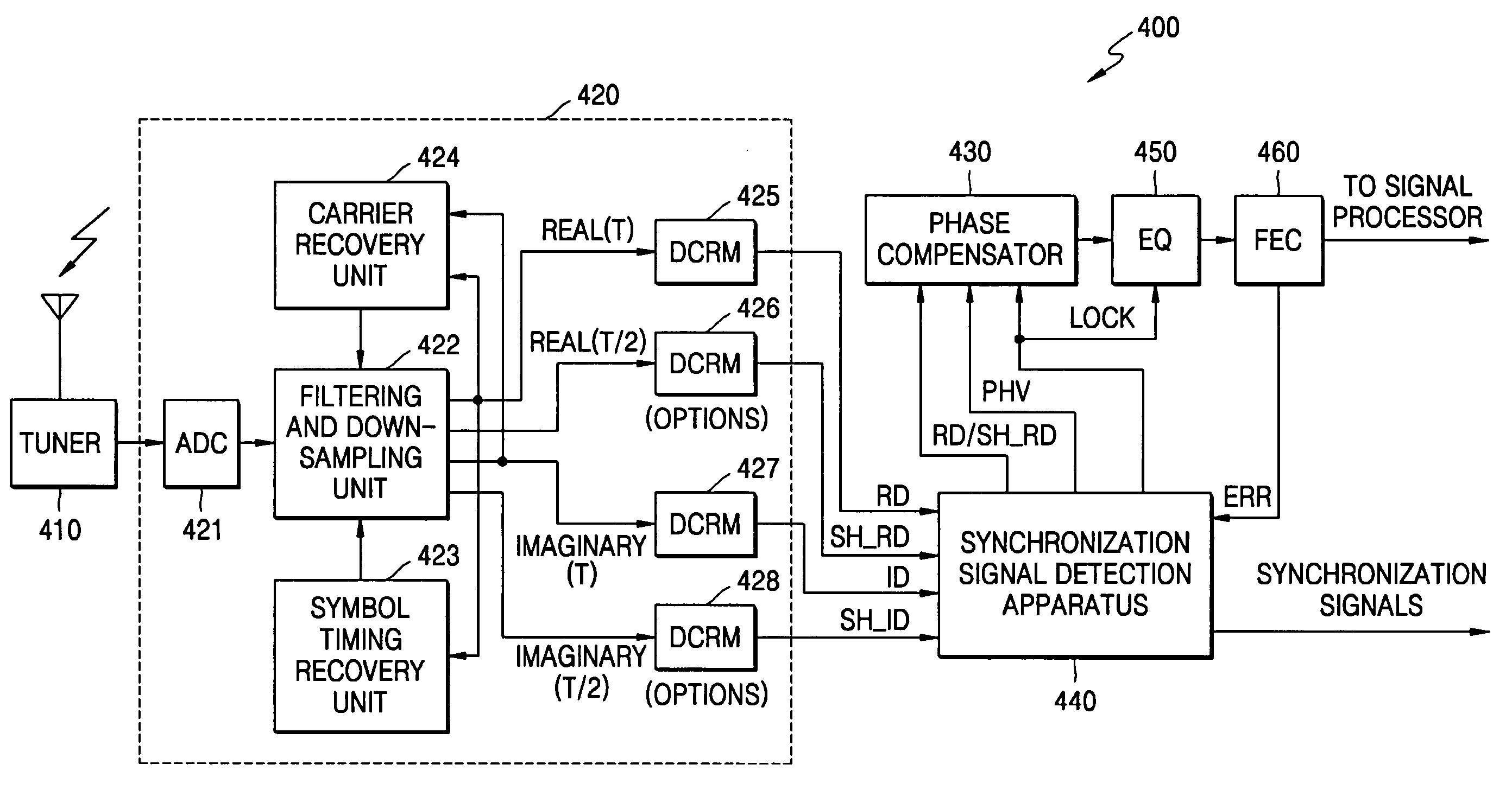
[0037]FIG. 4 is a block diagram of a DTV receiver 400 having a synchronization signal detection circuit 440 according to an exemplary embodiment of the present invention. Referring to FIG. 4, the DTV receiver 400 includes a tuner 410, a demodulator 420, a phase compensator 430, the synchronization signal detection circuit 440, an equalizer 450, and a FEC decoder 460.

[0038] A first and a second example of the synchronization signal detection circuit 440 (440a of FIG. 6 & 400b of FIG. 9), which detects VSB synchronization signals (e.g., using a first real component signal RD and a first imaginary component signal ID), will be described later with reference to FIGS. 6 and 9. The tuner 410 receives a high frequency VSB signal (transmitted through the air) via an antenna, tunes the received high frequency VSB signal to a channel allotted for the received high frequency VSB signal, extracts a baseband analog VSB signal from the tuned high frequency VSB signal, and outputs the baseband an...


PUM


Abstract

A synchronization signal detection circuit and method of a digital TV (DTV) receiver are provided. The synchronization signal detection circuit determines a precise main path by determining powers in consideration of the influence of multiple paths near signals located at a peak value location and guarantees a stable operation of an equalizer by using error values output from a decoder to generate a synchronization locking control signal. A power signal based on the correlation of the received signal with a PN511 sequence is filtered to compensate for a dynamic multipath distortion (e.g., due to other multipath signals near signals located at a peak value location). The magnitude of the filtered power signal is then compared (e.g., with a predetermined threshold value) to determine the position of the main path (e.g., at the peak value location, or at a pre or post multipath signal location).

Description

[0001] This application claims the priority under 35 U.S.C. §119 of Korean Patent Application No. 2004-0081350, filed on Oct. 12, 2004, in the Korean Intellectual Property Office, the disclosure of which is incorporated herein in its entirety by reference. BACKGROUND OF THE INVENTION [0002] 1. Field of the Invention p The present invention relates to a digital television (DTV) reception apparatus, and more particularly, to a synchronization signal detection circuit of a DTV receiver. [0003] 2. Description of the Related Art [0004] In recent years, the digitalization of broadcast television has been accelerated. Digital broadcast systems developed in Europe have been standardized under Terrestrial Digital Video Broadcasting (DVB-T), which is a standard of digital broadcasting based on orthogonal frequency division multiplexing (OFDM), while digital broadcast systems developed in the United States have been standardized under Vestigial Sideband (VSB). The Advanced Television SubCommit...

Claims


Application Information

Patent Timeline
IPC IPC(8): H04L27/22H04N5/232
CPCH04L7/042H04L27/066H04L2025/03382H04L2025/0349H04L2027/0067H04N5/08H04N5/211H04N5/4401H04N5/455H04N21/4302H04N21/4382H04N21/426H04N5/04
Inventor CHEON, JONG-HWANJEON, HYUN-BAE
Owner SAMSUNG ELECTRONICS CO LTD
Why Eureka
Try Eureka