
Powerhead of a power injection system

a technology of power injection system and injector head, which is applied in the field of contrast media injector system, can solve the problems of cumbersome operation of hand-operated movement buttons, difficulty in reading gauges or displays, and the possibility of accidentally injecting air into patients

Inactive Publication Date: 2006-04-13
LIEBEL FLARSHEIM CO
View PDF21 Cites 31 Cited by
  • Summary
  • Abstract
  • Description
  • Claims
  • Application Information

AI Technical Summary

Benefits of technology

[0011] Accordingly embodiments of the present invention relate to improving power injectors that are used to inject contrast media and other fluids in a patient or animal.
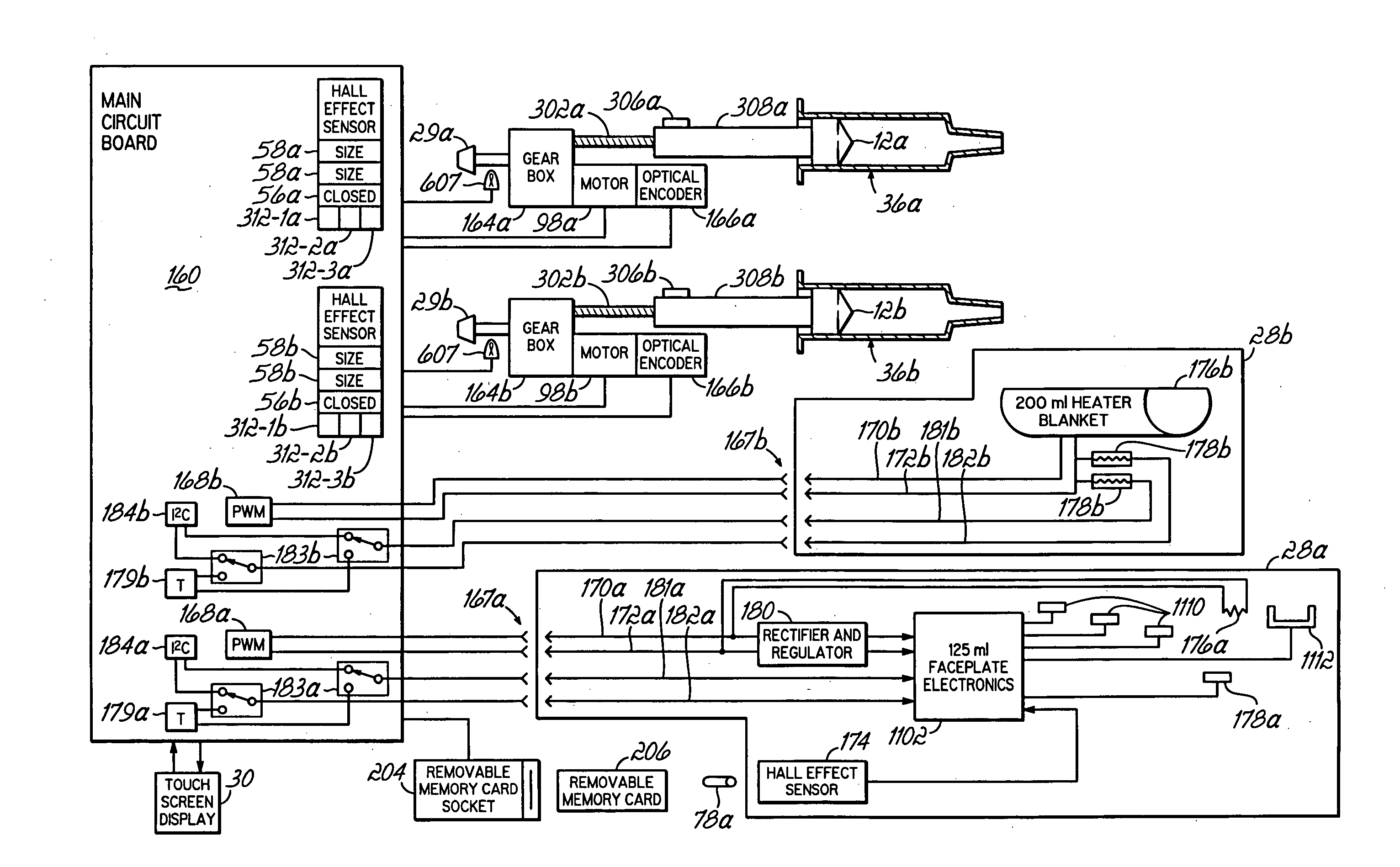
[0013] In a specific embodiment of this aspect, analog Hall-Effect sensors are utilized, enabling increased accuracy in determining the position of the magnet relative to the sensors.
[0015] Another aspect of the present invention relates to a manual control knob that is operatively coupled with the mechanism that moves the syringe ram. Because of this operative coupling, the knob rotates when the syringe ram is moving under programmed control. Also, the knob rotates at a speed that is directly indicative of the relative speed of the syringe ram. The knob is advantageously illuminated such that its rotation and speed of rotation is easily discernible. Accordingly, the control knob movement provides direct feedback about the operation of the syringe ram. In disclosed embodiments, this feedback is enhanced by changing the color of illumination of the knob to reflect the operative mode of the injector.
[0020] A further aspect of the present invention relates to an injector powerhead for injection from first and second syringes, having multiple syringe accessory connectors, and circuitry for identifying whether an accessory coupled to one of those connectors is associated with the first or second syringe, thus freeing the operator from the burden of connecting a syringe accessory to an appropriate one of the syringe connectors.

Problems solved by technology

Nevertheless, the potential for accidentally injecting air into a patient remains a serious safety concern.
Unfortunately, operators have found it cumbersome to use the hand-operated movement buttons and to read the injector head gauges and displays, for several reasons, not the least of which is the necessary tilting of the injector head between the upward, filling position to the downward, injection position, changing the positions of the hand-operated movement buttons relative to the operator, and at some tilt angles rendering the gauges or displays difficult to read.
Unfortunately, the necessity of incorporating a magnetic detector into the outer housing of the injector head increases the complexity and expense of manufacturing the injector head.

Method used


Image

  • Powerhead of a power injection system
  • Powerhead of a power injection system
  • Powerhead of a power injection system

Examples


Embodiment Construction

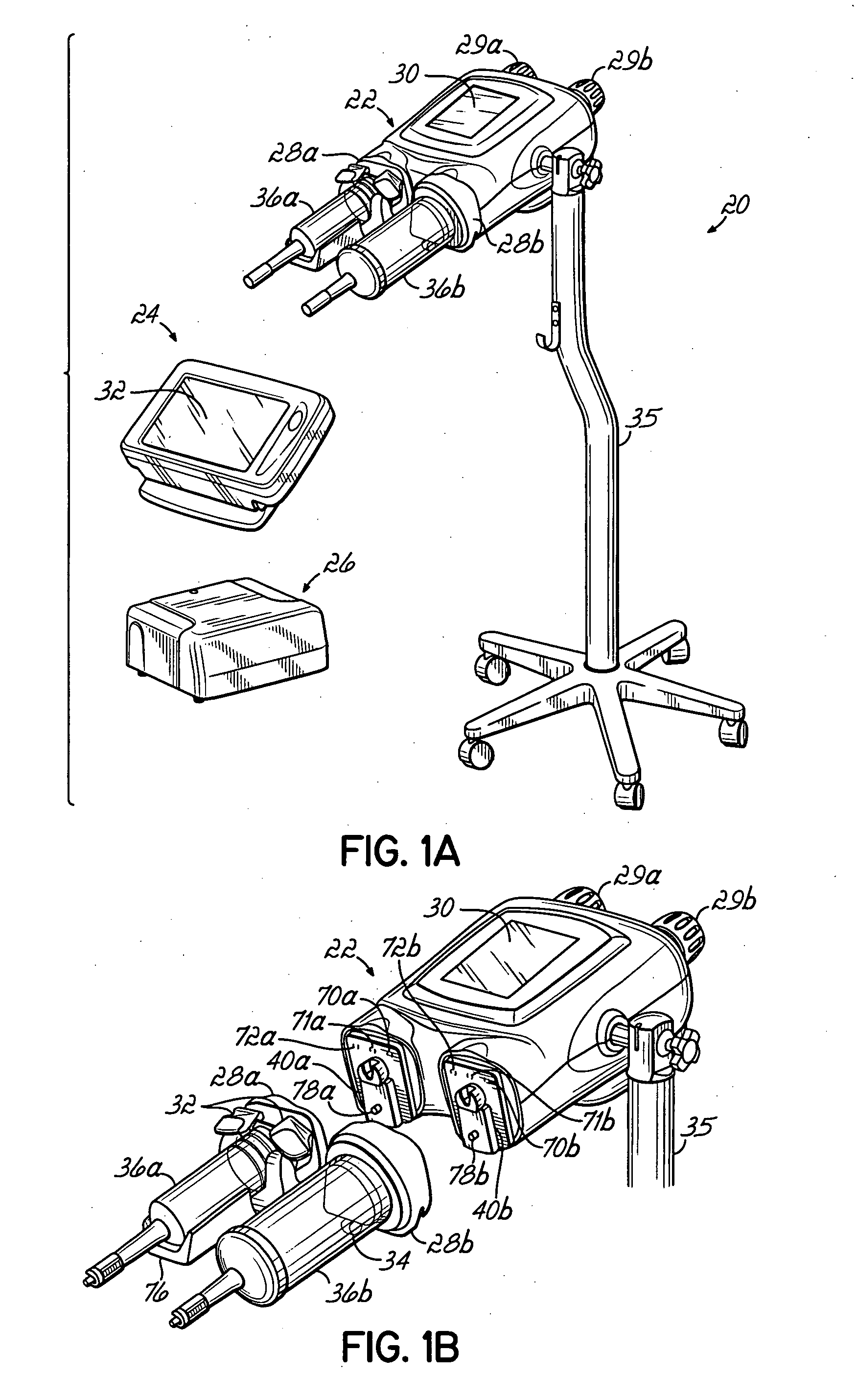
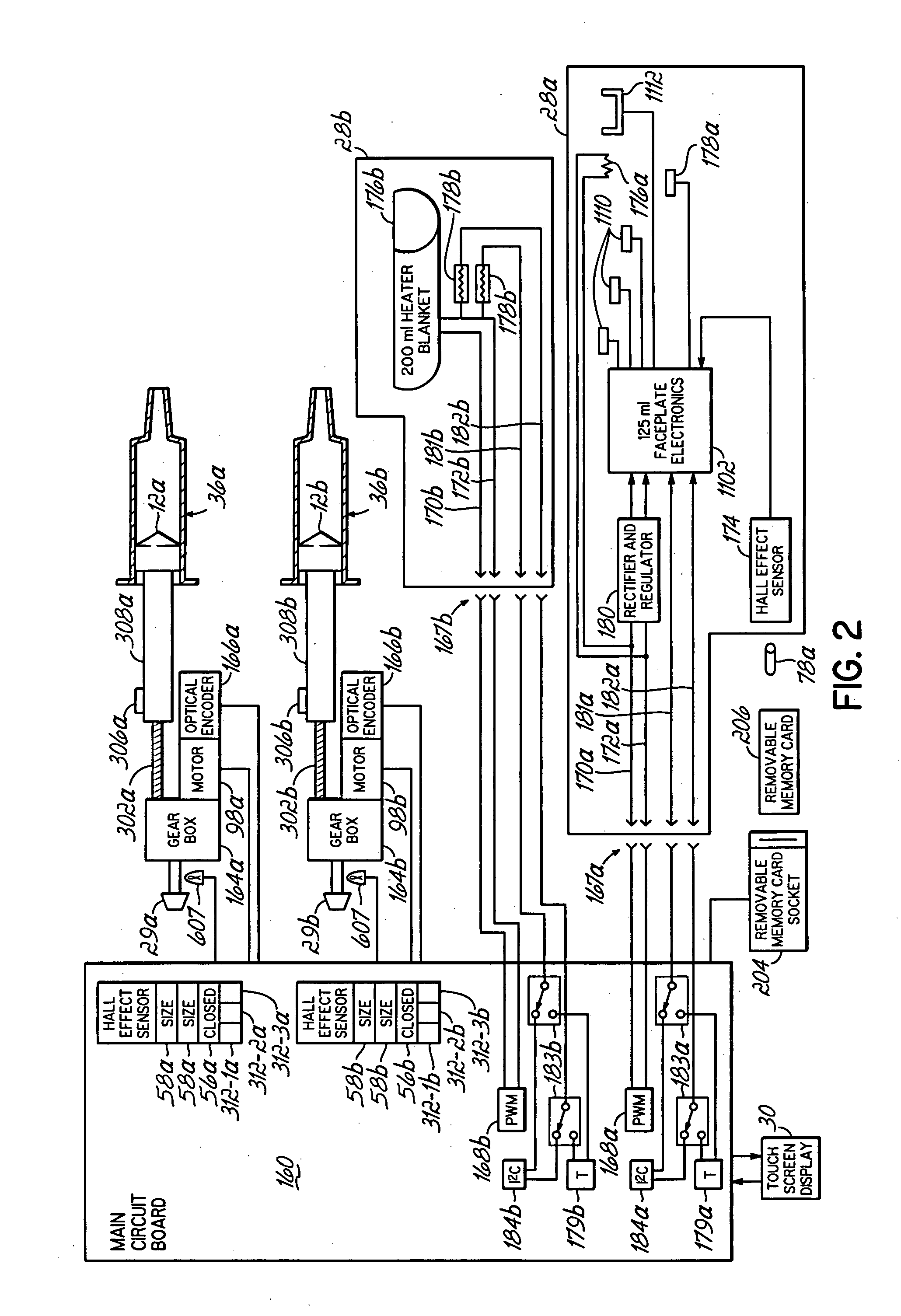
[0033] Referring to FIG. 1A, an injector 20 in accordance with the present invention includes various functional components, such as a powerhead 22, a console 24 and powerpack 26. Syringes 36a and 36b are mounted to the injector 20 in faceplates 28a and 28b of the powerhead 22, and the various injector controls are used to fill the syringe with, e.g., contrast media for a CT, Angiographic or other procedure, which media is then injected into a subject under investigation under operator or pre-programmed control.

[0034] The injector powerhead 22 includes a hand-operated knobs 29a and 29b for use in controlling the movement of the internal drive motors engaged to syringes 36a and 36b, and a display 30 for indicating to the operator the current status and operating parameters of the injector. The console 24 includes a touch screen display 32 which may be used by the operator to remotely control operation of the injector 20, and may also be used to specify and store programs for automat...


PUM


Abstract

A contrast media injection system includes detects the absolute position of the syringe ram using a non-contact sensor. A series of magnets and Hall-Effect sensors may be used or an opto-reflective system. Illuminated knobs that are connected to the drive mechanism for the syringe ram rotate with the drive and provide visual feedback on operation through the illumination. Analog Hall-Effect sensors are used to determine the presence or absence of magnets that identify the type of faceplate being used. The faceplates include control electronics, connected to the powerhead through connectors, which may be interchangeably used by the two faceplates. The faceplate electronics include detectors for automatically detecting the capacity of pre-filled syringes. Additional features include using historical data to provide optimum pressure limit values during an injection protocol, a removable memory device for storing and transferring information such as injection protocols and injector statistics, and password protection of such protocols.

Description

CROSS REFERENCE TO RELATED APPLICATION [0001] The present application is a divisional application of U.S. application Ser. No. 10 / 964,003, filed Oct. 13, 2005, entitled POWERHEAD OF A POWER INJECTION SYSTEM, which is related to co-pending application Ser. No. 10 / 964,002, filed Oct. 13, 2005, entitled POWERHEAD OF A POWER INJECTION SYSTEM. The present application is related to co-pending and concurrently filed application Serial No. ______, entitled POWERHEAD OF A POWER INJECTION SYSTEM and the two divisional applications of application Ser. No. 10 / 964,002, filed Oct. 13, 2005, entitled POWERHEAD OF A POWER INJECTION SYSTEM. All of these applications are hereby incorporated by reference herein in their entirety.FIELD OF THE INVENTION [0002] The present invention relates to contrast media injector systems and, more particularly to improvements thereto. BACKGROUND OF THE INVENTION [0003] In many medical environments, a medical fluid is injected into a patient during diagnosis or treatm...

Claims


Application Information

Patent Timeline
IPC IPC(8): A61M5/00
CPCA61M5/007A61M5/14546A61M5/14566A61M5/16827A61M5/1785A61M2205/3389A61B6/548A61M2205/52A61M2205/587A61M2205/6054A61M2205/6063A61M2205/3306A61M2205/3317A61M2205/502
Inventor NEER, CHARLES S.SMALL, JAMES R.
Owner LIEBEL FLARSHEIM CO
Learn More