Operating position select device for automatic transmission

a select device and automatic transmission technology, applied in mechanical control devices, process and machine control, instruments, etc., can solve the problems of reducing design freedom concerning the installation location of the select lever unit and/or the layout of the passenger compartment, and the operating force of the driver is limited to a certain exten

Inactive Publication Date: 2006-04-20
CALSONIC KANSEI CORP
View PDF3 Cites 28 Cited by
  • Summary
  • Abstract
  • Description
  • Claims
  • Application Information

AI Technical Summary

Benefits of technology

[0010] According to the first aspect of the present invention there is provided an operating position select device for an automatic transmission whose operation modes are shiftable, the operating position select device comprising a select lever unit having a select lever that is operated by a driver between a plurality of select positions corresponding to the operation modes, a first connecting member mechanically connected with and movable with the select lever; an operating position sensor detecting an operating position of the select lever, a mode shift unit mounted on the automatic transmission to shift operation modes of the automatic transmission, a second connecting member mechanically connected with the mode shift unit to shift positions thereof, the se

Problems solved by technology

The conventional art, however, has a problem that the select lever unit needs a long select lever in order to operate it without a large operating force of the driver, which reduces design freedom concerning an installation location of the select lever unit and/or a layout of a passenger compartment.
Namely, the operating torque, generated by the operating force on the select lever, has to be larger than torque caused by the sum of the frictional resistance in the connecting mechanism a

Method used


Image

  • Operating position select device for automatic transmission
  • Operating position select device for automatic transmission
  • Operating position select device for automatic transmission

Examples


first embodiment

[0116] In order to avoid such the above situation, the operating position select device 1 of the first embodiment is constructed so as to judge whether or not an output deviation of the sensors 61 and 62 is within a normal range when the motor 2 is not actuated and determine drive of the motor 2 based on its judgment.

[0117]FIG. 9 shows a flowchart of an abnormal diagnosis process executed by the control unit 3.

[0118] At step S11, the abnormal diagnosis part 33 judges whether or not the assist control is halted. If YES, the flow goes to step S12, while, if NO, the flow returns.

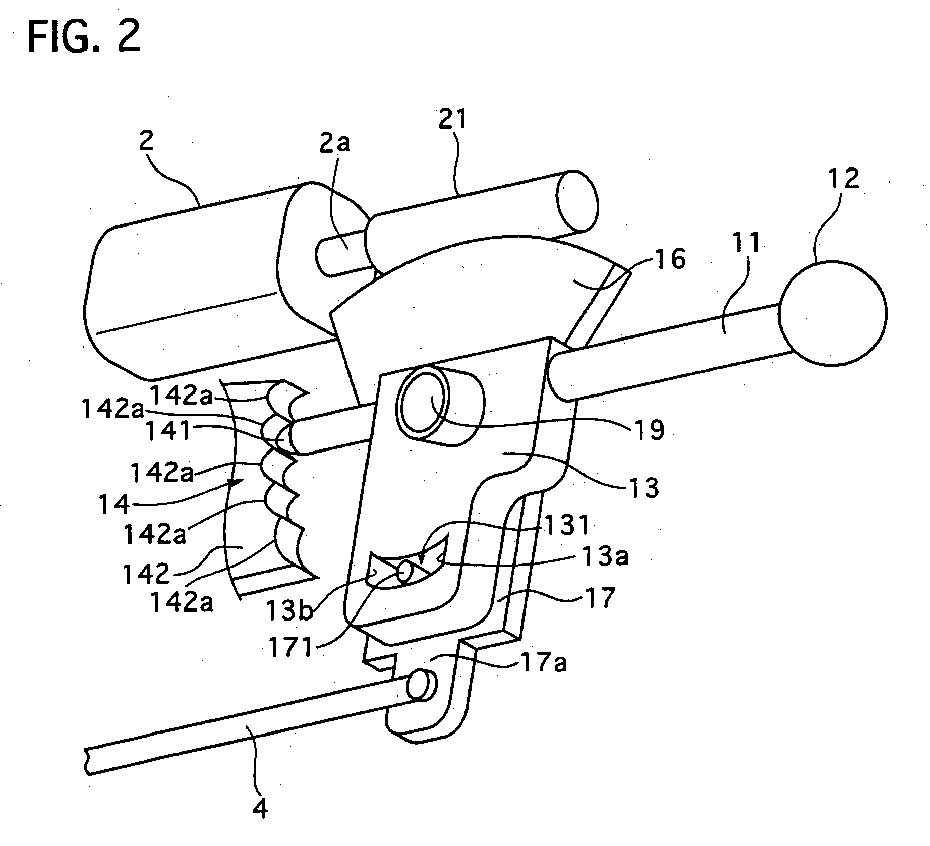
[0119] At the step S12; the part 33 judges, based on a relative displacement between an operating angle and an assist angle, whether or not a numerical value of the relative displacement is larger than a predetermined value D / 2. D is a maximum possible relative angle in which the first connecting member 13 and the second connecting member 17 can move relatively to each other, and determined by a travel length...

second embodiment

[0131] Next, an operating position select device of a second embodiment according to the present invention will be described with reference to the accompanying drawings of FIGS. 11 and 12.

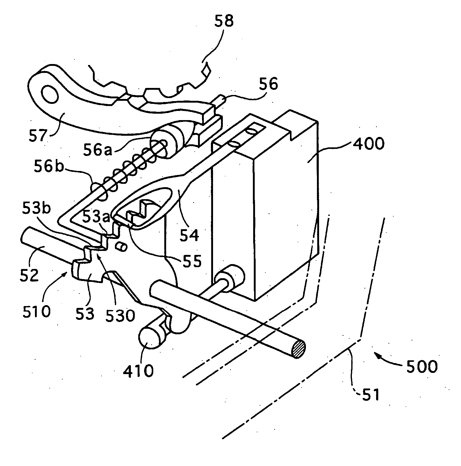
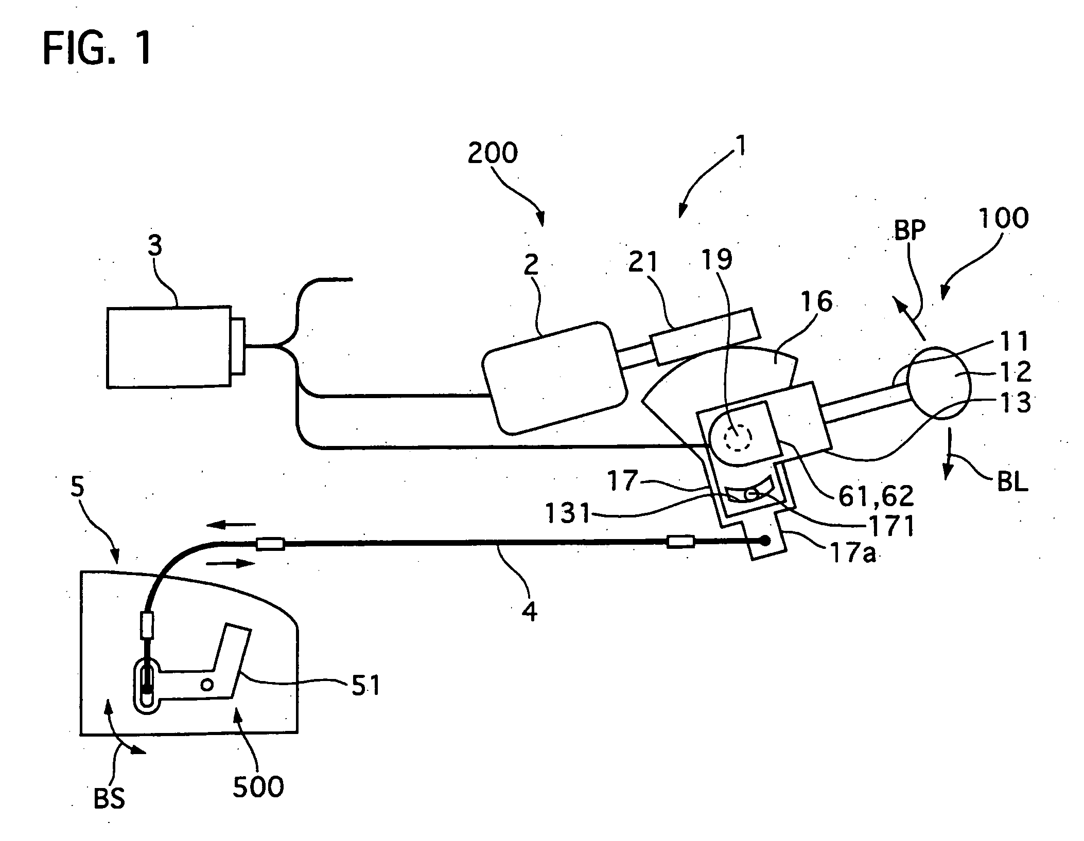
[0132] Referring to FIG. 11, this operating position select device is constructed similarly to that of the first embodiment shown in FIGS. 1 to 4 except a partial modification of an abnormal diagnosis part 36 in a control unit 3 and use of an inhibitor switch 66. The inhibitor switch 66 is mounted on an automatic transmission to detect a selected position AIN of a mode shift unit 500, and outputs a selected position signal. In this embodiment, the selected position AIN is a selected position angle detected by the inhibitor switch 66 so as to fit its physical quantity to an operating angle AOP of a select lever 11. The inhibitor switch 66 acts as a select position sensor of the present invention.

[0133] The abnormal diagnosis part 36 is electrically connected to the inhibitor switch 66 and an operat...

third embodiment

[0152] Next, an operating position select device of a third embodiment according to the present invention will be described with reference to the accompanying drawings of FIGS. 13 and 14.

[0153] Referring to FIG. 13, this operating position select device is constructed similarly to that of the first embodiment shown in FIGS. 1 to 4 except a partial modification of an abnormal diagnosis part 37 in a control unit 3 and use of an inhibitor switch 66. The inhibitor switch 66 is mounted on an automatic transmission to detect a selected position AIN of a mode shift unit 500, corresponding to the assist angle in the first embodiment, and outputs a selected position signal. In this embodiment, the selected position AIN is a selected position angle detected by the inhibitor switch 66 so as to fit-its physical quantity to an assist angle ASP of the mode shift unit 5. The inhibitor switch 66 acts as a select position sensor of the present invention.

[0154] The abnormal diagnosis part 37 is elec...


PUM


Abstract

An operating position select device has a select lever unit, a mode shift unit to shift operation modes of the automatic transmission, and an assist actuator controlled by a control unit. A first connecting member of the select lever and a second connecting member of the mode shift unit are relatively movable to a limit amount to each other and integrally movable beyond the limit amount with each other. The positions of the members are detected by an operating position sensor and an assist position sensor, respectively. The actuator is driven so that a difference between an operating position and an assist position may be reduced, but prohibited from driving when the difference is kept out of a permissible range for a predetermined period during rest of the actuator.

Description

BACKGROUND OF THE INVENTION [0001] 1. Field of the Invention [0002] The present invention relates to an operating position select device for an automatic transmission by which a driver can select by operating a select lever one of select mode positions corresponding to a plurality of operation modes of the automatic transmission. [0003] 2. Description of the Related Art [0004] An operating position select device for an automatic transmission of this kind is disclosed in Japanese patent laying-open publication (Tokkaihei) No. 9-323559. This select device includes a select lever unit disposed near a driver's seat in a passenger compartment and a mode shift unit mounted on an automatic transmission. The select lever unit has a select lever manually operated by a driver and is connected with the mode shift unit by a connecting mechanism, such as a control cable, or a connecting linkage, which transmits an operating force applied on the select lever by the driver to the mode shift unit t...

Claims


Application Information

Patent Timeline
IPC IPC(8): G05G5/00F16H61/12
CPCF16H59/10F16H61/12F16H61/2807F16H2061/326Y10T74/20085F16H2061/323Y10T74/19251Y10T74/2003F16H2061/301
Inventor OTSUKA, TAKASHIHIROTA, YUKITSUGUOSAMURA, KENSUKENAGANO, MASAHARUKOBAYASHI, SHINYA
Owner CALSONIC KANSEI CORP
Why Eureka
Try Eureka