Electrical charge air compressor provided with an integrated air cooling system

a charge air compressor and integrated cooling system technology, which is applied in the direction of positive displacement liquid engines, liquid fuel engines, pipe pumps, etc., can solve the problems of high-speed operation of electric auxiliary compressors, and reducing the efficiency of charge air pressur

Inactive Publication Date: 2006-04-20
ROBERT BOSCH GMBH
View PDF8 Cites 34 Cited by
  • Summary
  • Abstract
  • Description
  • Claims
  • Application Information

AI Technical Summary

Problems solved by technology

These types of exhaust-gas turbochargers have the known disadvantage of delayed and inadequate response characteristics at low rpms of the internal combustion engine (“turbocharger gap”).
The short-term, very high-speed operation of the electric auxiliary compressor produces very high thermal stress to these system components.
Such a system has the disad...

Method used


Image

  • Electrical charge air compressor provided with an integrated air cooling system
  • Electrical charge air compressor provided with an integrated air cooling system
  • Electrical charge air compressor provided with an integrated air cooling system

Examples


Embodiment Construction

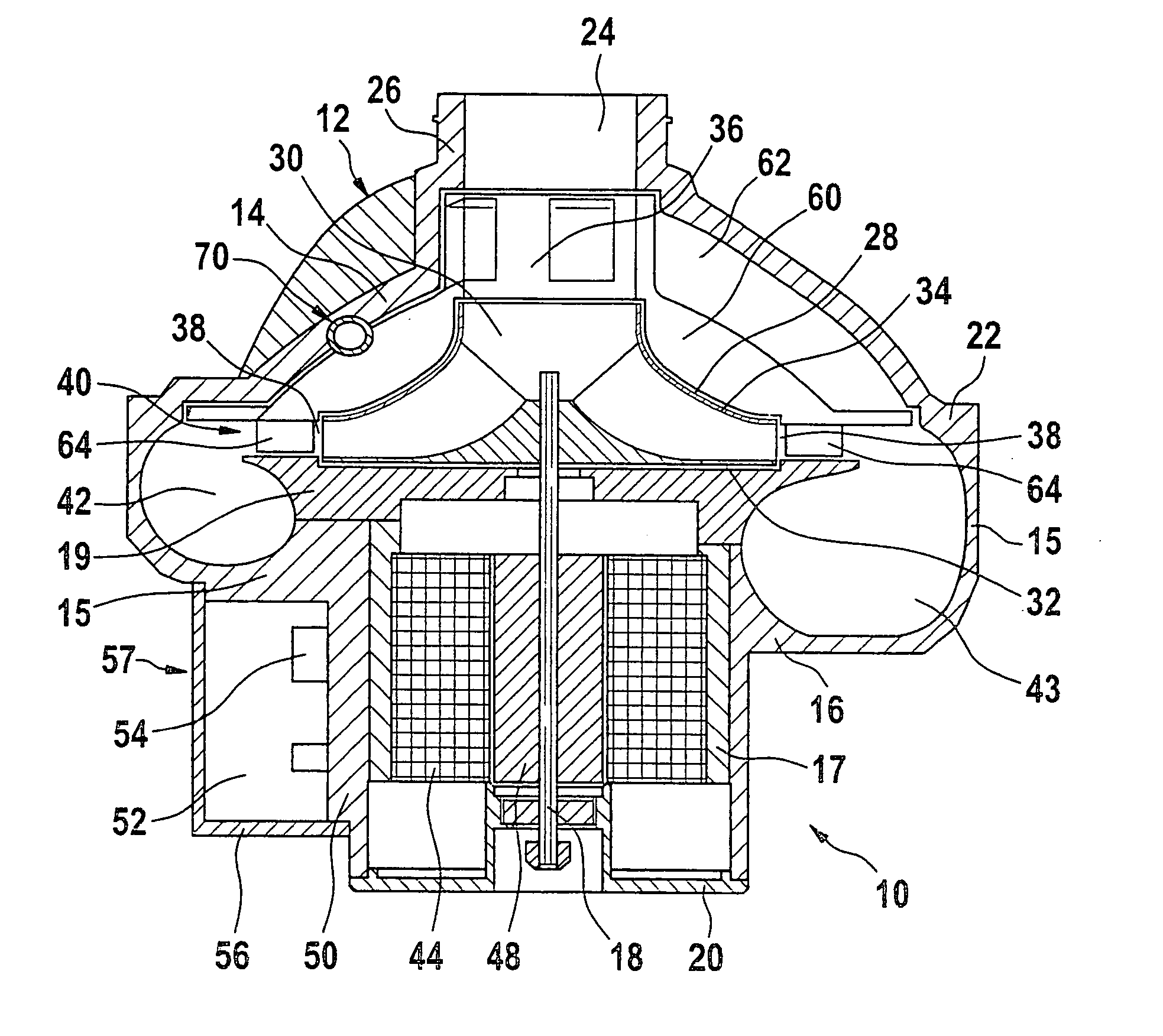
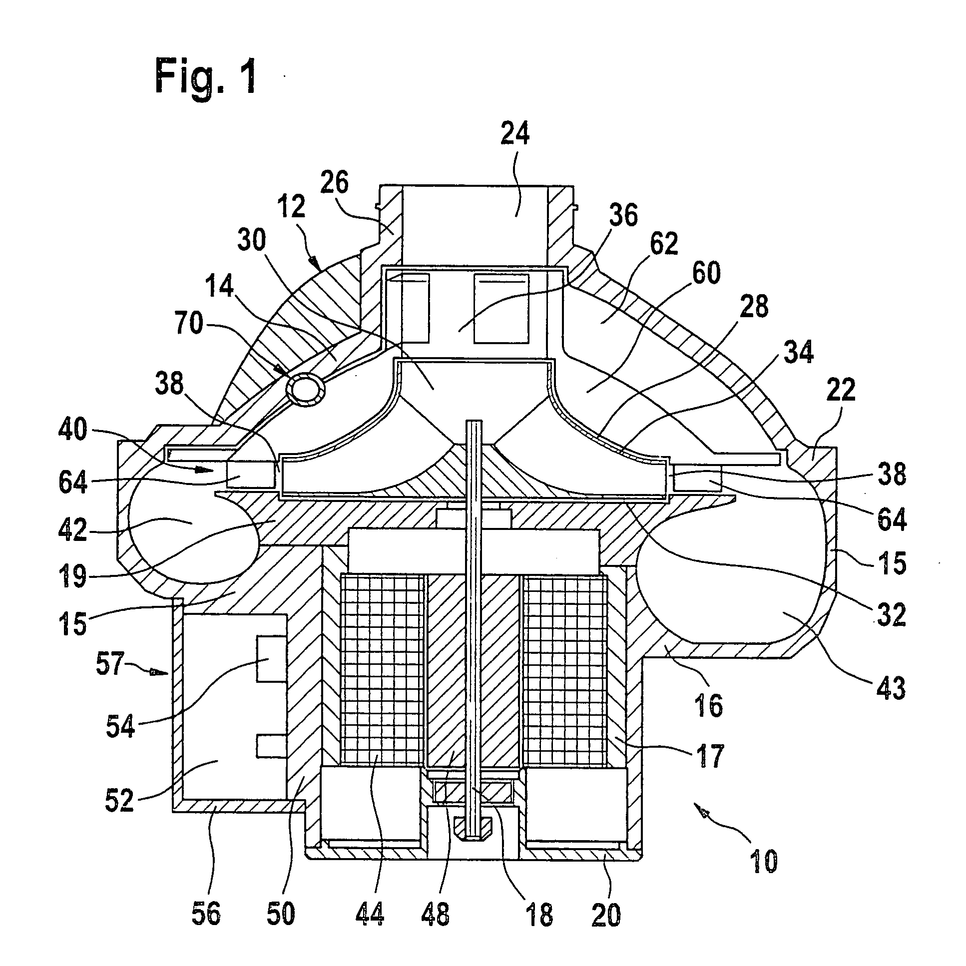
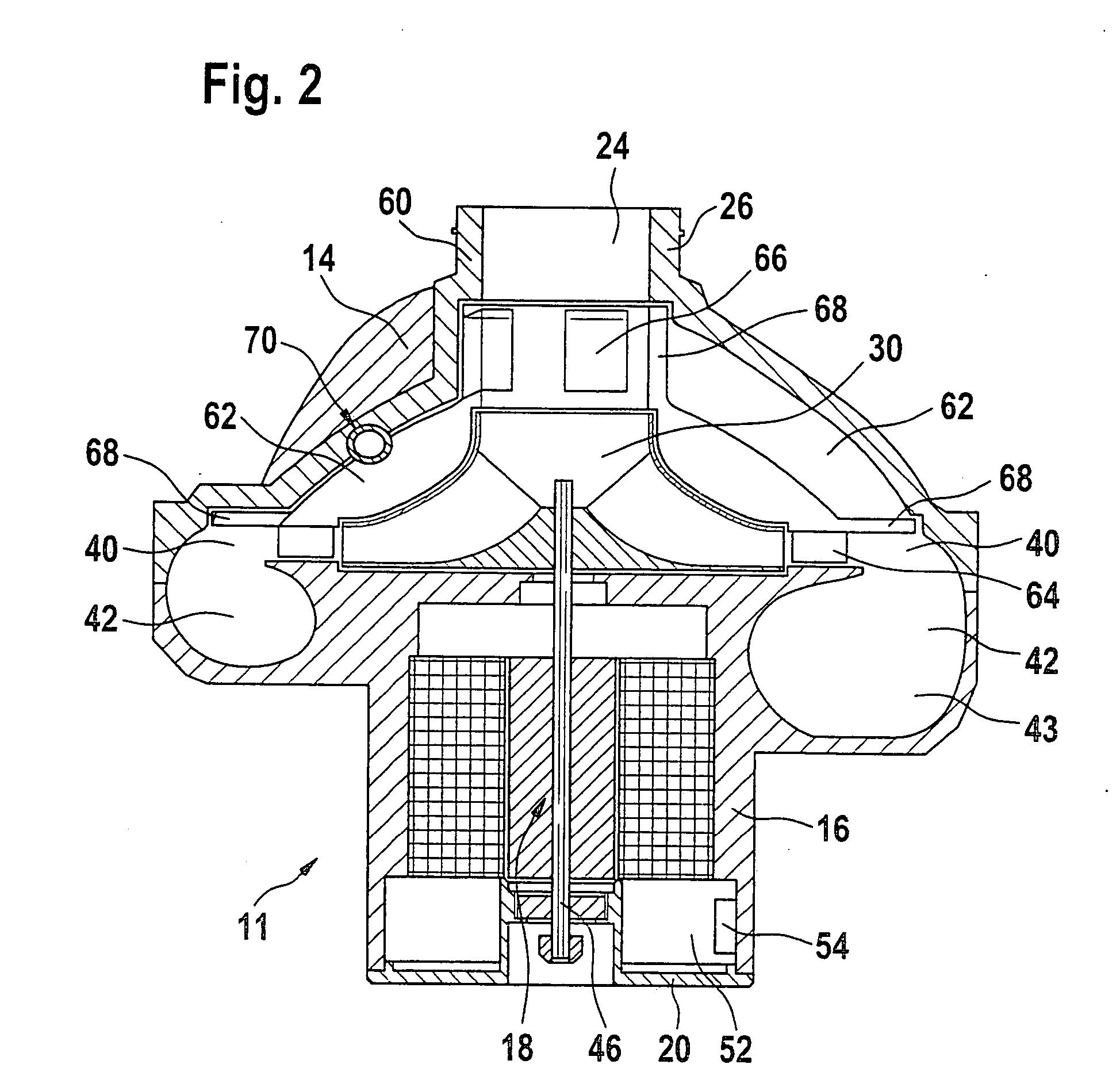
[0031]FIG. 1 shows a schematic representation of a first exemplary embodiment of the device in accordance with the invention to compress combustion air. The compressor 10 features a housing 12, which is embodied as several pieces in the exemplary embodiment in FIG. 1. The housing of the compressor essentially includes a first housing part 14 for the actual compressor head 22 of the device (also called compressor part of the device in the following) and a second housing part 16, which surrounds the driving means for the compressor and, in the exemplary embodiment in FIG. 1, essentially includes an electric motor 18 driving the compressor along with associated electronic components. The second housing part 16 of the compressor in accordance with the exemplary embodiment in FIG. 1 is in itself constructed of three parts for manufacturing-related reasons. The housing part 16 includes the actual motor housing 17 of the driving electric motor 18, which is embodied as a pole pot or as a tu...


PUM


Abstract

The invention relates to a device to compress combustion air, in particular a device to compress combustion air for a combustion engine of a motor vehicle, with a housing (12), with at least one compressor impeller (30) arranged in a compression area (28) of a first housing part (14), which is arranged in the flow direction between an air inlet (24) and an air outlet (43) of the housing (12), as well as with an electric motor (18) arranged in a second housing part (16) of the housing (12) to operate the compressor impeller (30). It is proposed in accordance with the invention that a flow channel (42) running in the circumferential direction of the first housing part (12) and connecting the compression space (28) with the air outlet (43) surrounds the electric motor (18) at least partially.

Description

PRIOR ART [0001] The invention relates to a device to compress combustion air, in particular an electrically operated charge-air compressor with the features of the pre-characterizing clause of Claim 1. [0002] Increasing the power density of an internal combustion engine by compressing the air required for combusting the fuel by means of an exhaust-gas turbocharger is known. In this case, the exhaust-gas turbocharger features a turbine, which is arranged in the exhaust-gas flow of the combustion engine and which drives a compressor arranged in the charge-air feed of the internal combustion engine. [0003] These types of exhaust-gas turbochargers have the known disadvantage of delayed and inadequate response characteristics at low rpms of the internal combustion engine (“turbocharger gap”). [0004] In order to improve the charge-air feed, especially in the range of lower rpms of the internal combustion engine, supporting the exhaust-gas turbocharger by means of an electric auxiliary dr...

Claims


Application Information

Patent Timeline
IPC IPC(8): F02B33/00F02B33/40F02B39/00F02B39/10F04D25/08F04D27/02F04D29/42
CPCF02B33/40F02B39/00F02B39/005F02B39/10F04D25/082F04D27/0215F04D29/4233F04D25/0606F04D29/5806H01L23/467
Inventor BOLZ, MARTIN-PETER
Owner ROBERT BOSCH GMBH
Why Eureka
Try Eureka