Split access fan shroud

Inactive Publication Date: 2006-04-20
INNIGER STEVEN W +5
View PDF18 Cites 14 Cited by
  • Summary
  • Abstract
  • Description
  • Claims
  • Application Information

AI Technical Summary

Benefits of technology

[0002] Mobile vehicles, especially heavy-duty commercial vehicles, are commonly configured with the engine located longitudinally forward of the cab and mounted to a set of frame rails, which form the structure of the vehicle. Forward of the engine is a radiator or heat exchanger, which serves to reject waste heat created by the engine in powering the vehicle. This area of the engine compartment is often tightly packed with engine and vehicle accessories and subsystems, such as fluid and air conduits, pumps, reservoirs, generators, and other devices. In the center of a

Problems solved by technology

As a result, the shroud presented a barrier to servicing the fan drive itself, the FEAD and its belt, and any of a number of other e

Method used


Image

  • Split access fan shroud
  • Split access fan shroud
  • Split access fan shroud

Examples


Embodiment Construction

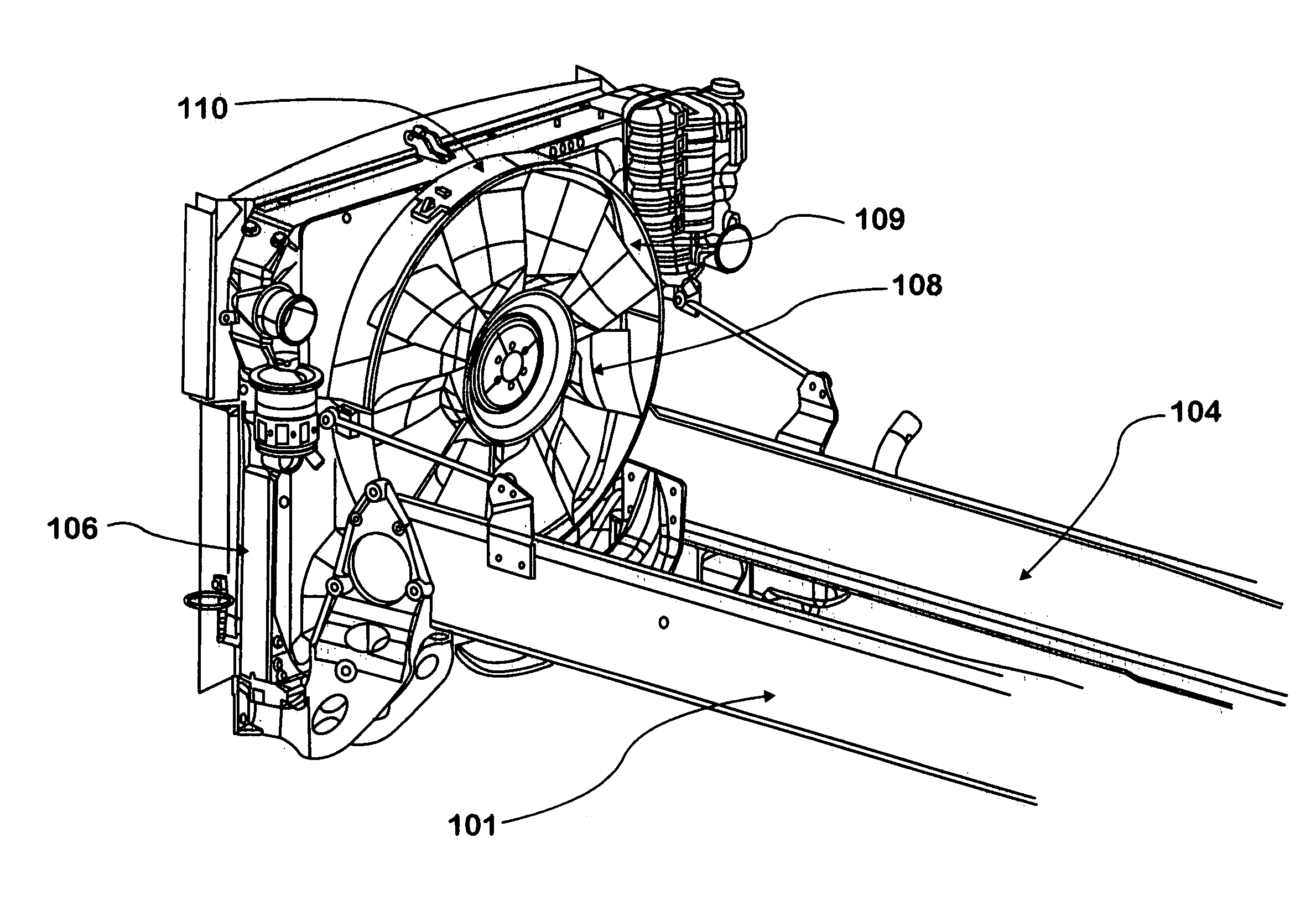
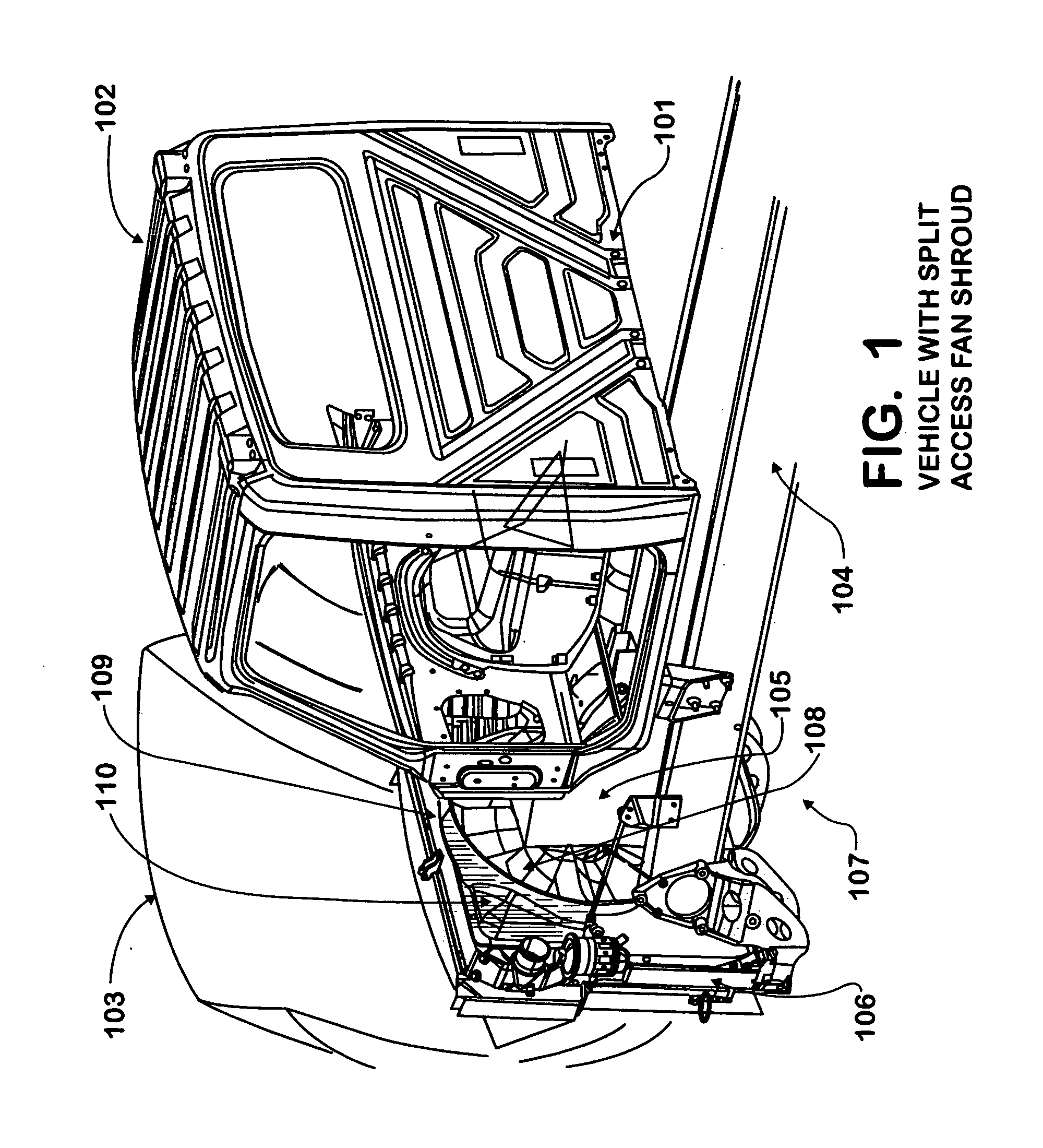
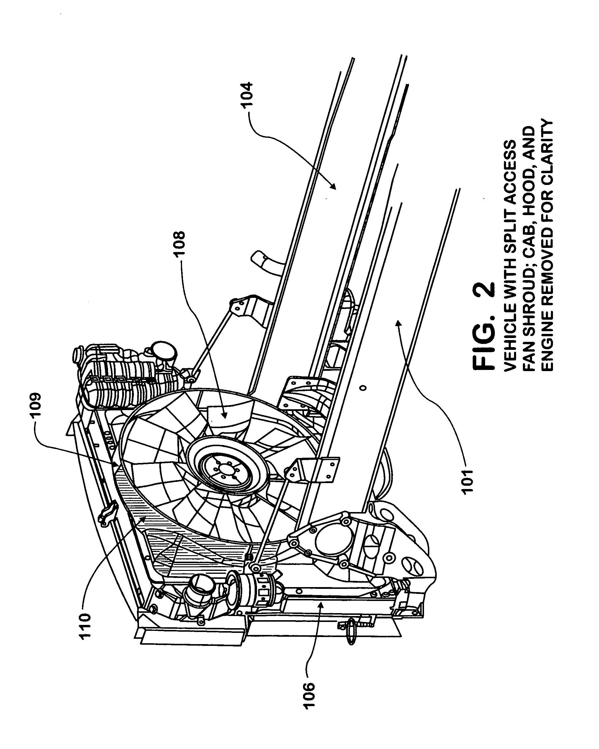
[0024] The vehicle 101 shown in FIG. 1 has a cab 102 and a hood 103 engaged to a chassis 104. The chassis 104 has an engine 105, which provides power for propulsion of vehicle 101, and in so doing creates waste heat. The chassis 104 also has a radiator 106, located forward of engine 105, relative to vehicle 101 forward movement, which serves to reject said heat to the surrounding environment 107. Attached to and driven by engine 105 in a conventional manner is fan 108, which serves to increase heat transfer from radiator 106 to the surrounding environment 107, by increasing airflow through radiator 106 when vehicle 101 is slowed or stopped. The fan 108 may be driven either directly or indirectly by the engine 105. The radiator 106 has a shroud 109, which channels said airflow through fan 108 in a conventional manner, and prevents recirculation thereof, thereby increasing the operating efficiency of radiator 106. In accordance with the invention disclosed herein, shroud 109 is provid...


PUM


Abstract

A fan shroud for a mobile vehicle having an opening therein for the easy removal of the cooling fan therethrough. A removable shroud section is provided in various embodiments, exemplifying efficient modes of manufacture for said removable shroud section and its attachment to said fan shroud.

Description

BACKGROUND OF INVENTION [0001] This invention relates to a radiator shroud with a removable shroud section that provides for easy removal of the cooling fan from a mobile vehicle. Specifically, multiple embodiments are disclosed by means of which a shroud with a removable shroud section may be readily and inexpensively manufactured and incorporated into a mobile vehicle. SUMMARY [0002] Mobile vehicles, especially heavy-duty commercial vehicles, are commonly configured with the engine located longitudinally forward of the cab and mounted to a set of frame rails, which form the structure of the vehicle. Forward of the engine is a radiator or heat exchanger, which serves to reject waste heat created by the engine in powering the vehicle. This area of the engine compartment is often tightly packed with engine and vehicle accessories and subsystems, such as fluid and air conduits, pumps, reservoirs, generators, and other devices. In the center of all of this hardware is the engine coolin...

Claims


Application Information

Patent Timeline
IPC IPC(8): B60H1/00F04D29/40B60R99/00
CPCF04D29/545F04D29/582
Inventor INNIGER, STEVEN W.KUHN, STEVEN P.BROWN, GEORGE A.FALENDYSZ, GARYVOISIN, DANIELVAUGHN, JAMES
Owner INNIGER STEVEN W
Why Eureka
Try Eureka