Method and control system for directional drilling

a control system and directional drilling technology, applied in the direction of directional drilling, survey, borehole/well accessories, etc., can solve the problems of increasing friction between the drill string and the bore hole, reducing the friction in the bore hole, and reducing the cost of subterranean drilling

Active Publication Date: 2006-04-20
PASON SYST
View PDF7 Cites 42 Cited by
  • Summary
  • Abstract
  • Description
  • Claims
  • Application Information

AI Technical Summary

Benefits of technology

[0010] In one aspect, the invention features a method for reducing friction in a bore hole during directional drilling. A drill string motor is commanded to rotate at a constant speed in a forward direction and the constant speed in a reverse direction for a first duration and a second duration, respectively, for at least one oscillation cycle such that an averaged absolute angle of the drill sting is substantially the same as a target rotation angle. In one embodiment, the target rotation angle for the drill string is modified in response to measurement while drilling (MWD) data. In another embodiment, the averaged absolute angle of the drill string is determined for at least one oscillation cycle, the difference between the averaged absolute angle and the target rotation angle is determined, and the first and second durations are adjusted in response to the difference. The drill string motor is commanded to rotate at the constant speed in the forward direction and the reverse direction for the adjusted first duration and the adjusted second duration, respectively, for at least one subsequent oscillation cycle.
[0011] In another aspect, the invention features a control system for directional drilling. The control system includes a rotation sensor, an absolute angle estimator, an oscillation control module and an operator control panel. The rotation sensor provides rotation data in response to a rotation angle of a drill string. The absolute angle estimator communicates with the rotation sensor to receive rotation data and determine an absolute rotation angle of the drill string. The oscillation control module includes a closed loop speed controller and communicates with the absolute angle estimator. The oscillation control module commands the drill string motor to rotate at a constant speed in a forward direction and the constant speed in a reverse direction for a first duration and a second duration, respectively, for at least one oscillation cycle. The operator control panel communicates with the oscillation control module and is adapted to receive MWD data. The operator control panel has at least one user input device for an operator to adjust the first duration and the second duration for at least one subsequent oscillation cycle.
[0012] In still another aspect, the invention features a control system for directional drilling. The control system includes a rotation sensor, an absolute angle estimator, an error module and an oscillation control module. The rotation sensor provides rotation data in response to a rotation angle of a drill string. The absolute angle estimator communicates with the rotation sensor to receive rotation data and determine an absolute rotation angle of the drill string. The error module is configured to receive a target rotation angle and to receive MWD data indicating the orientation of a toolface of a drilling tool. The error module generates an error signal in response to a difference between the target rotation angle and the MWD data. The oscillation control module communicates with the absolute angle estimator and the error module, and includes a closed loop speed controller. The oscillation control module commands the drill string motor to rotate at a constant speed in a forward direction and the constant speed in a reverse direction for a first duration and a second duration, respectively, for at least one oscillation cycle. The first duration and the second duration are responsive to the error signal.

Problems solved by technology

Subterranean drilling is an expensive process during which a bore hole is drilled through the earth to gain access to a desired resource such as an oil or gas deposit.
Friction generally slows the drilling process by reducing the force applied to the drill bit.
Although change of the bore hole direction is typically accomplished through a gradual deflected over hundreds of feet or more so that the drill string bends gradually, the friction between the drill string and the bore hole generally increases.
Similar to straight path drilling, the rate of penetration during directional drilling is adversely affected by friction between the drill string and bore hole.
Due to the torsional spring properties of the drill string, the rotation of the drill string at the surface does not match the rotation of the drill string at other positions along its length.
Thus the frictional limitation on the drilling process can be reduced by back and forth rotation of the surface portion of the drill string within appropriate angular limits without changing the orientation of the toolface although in practice it can be difficult to achieve the desired back and forth rotation without affecting the orientation of the toolface during directional drilling.

Method used


Image

  • Method and control system for directional drilling
  • Method and control system for directional drilling
  • Method and control system for directional drilling

Examples


Embodiment Construction

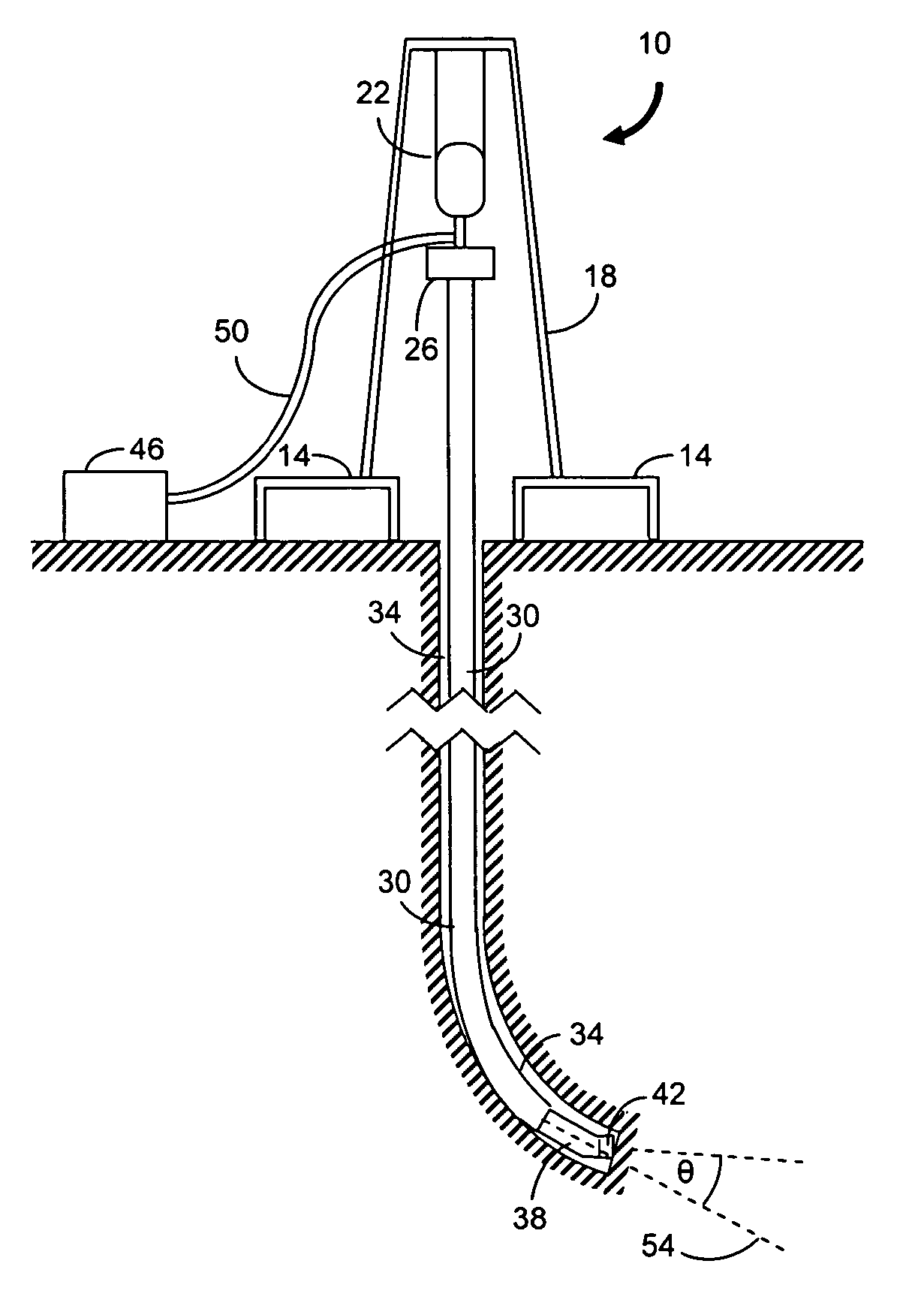
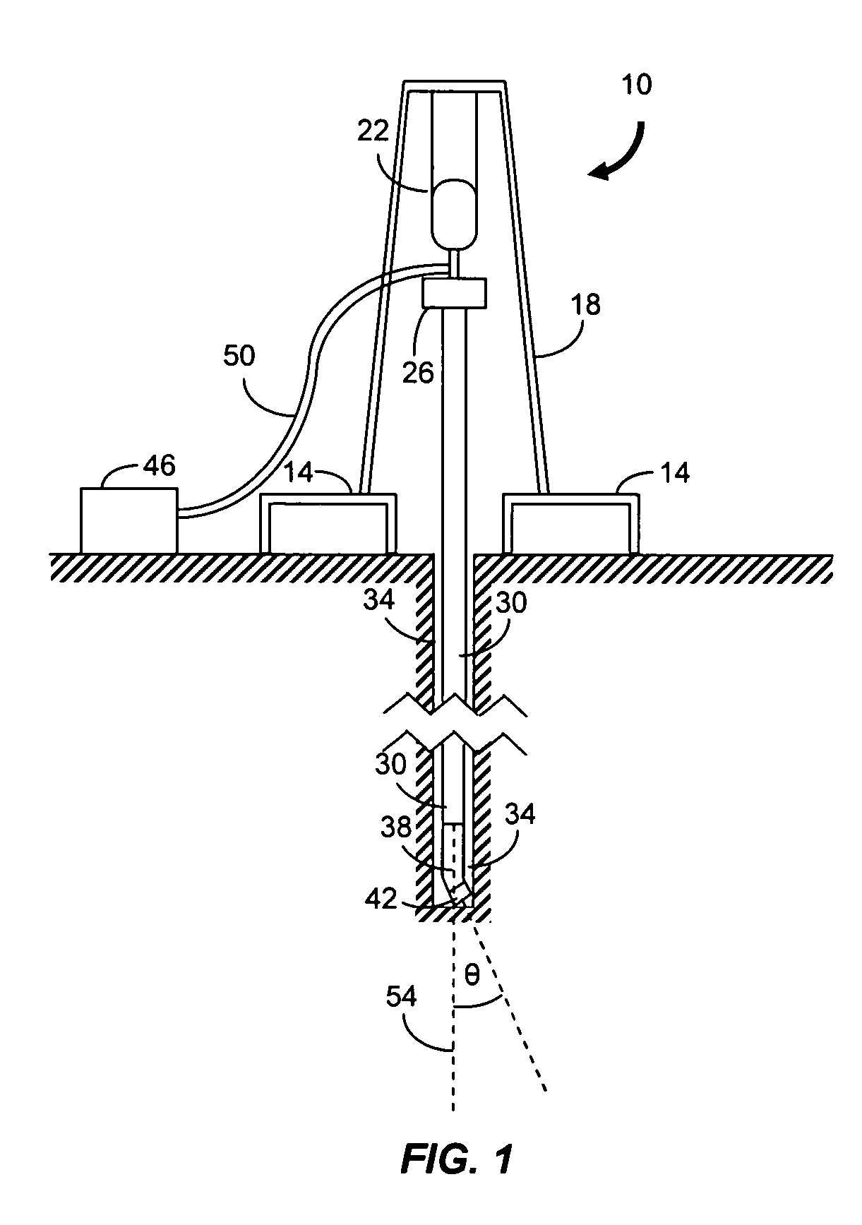
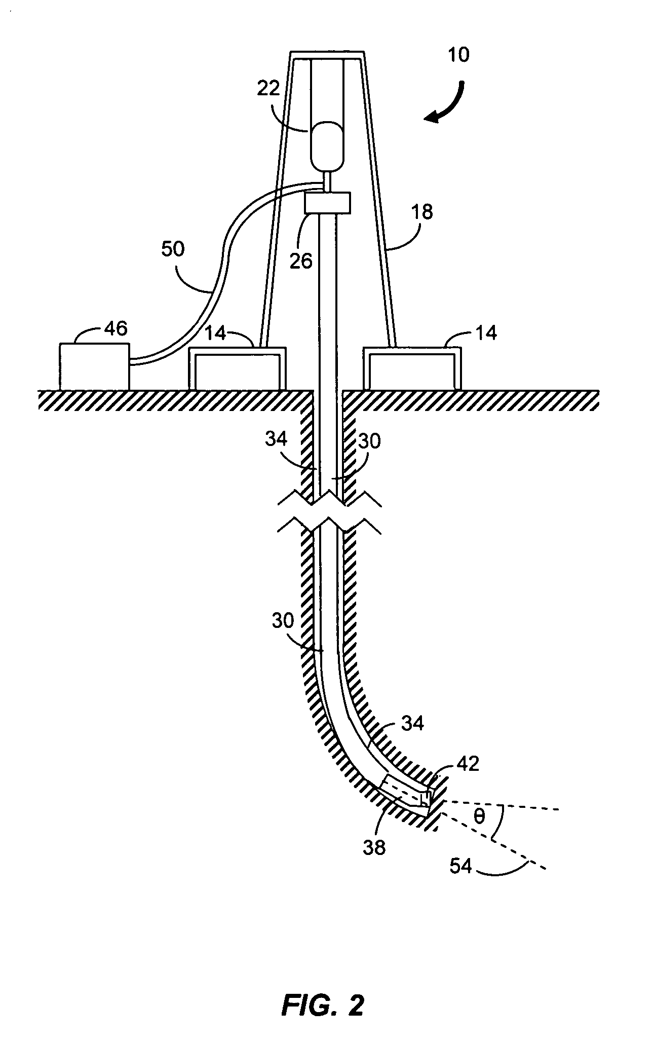
[0021] In brief overview, the present invention relates to a method and control system for directional drilling. The method includes commanding a motor to rotate a drill string at a constant speed in a forward direction and at the same constant speed in a reverse direction for a first duration and a second duration, respectively. The durations can be adjusted to achieve or maintain the desired orientation of a drilling tool based, for example, on “measurement while drilling” (MWD) data. Advantageously, the method reduces the effects of friction in a bore hole, leading to an increase in the penetration rate.

[0022] Referring to FIG. 1, a land-based drilling rig 10 includes a platform 14 and derrick 18. Lifting gear 22 attached to the derrick 18 provides for vertical positioning of a top drive 26. The top drive 26 supports and rotates a drill string 30 which extends along the length of a bore hole 34. The drill string 30 includes any number of coupled sections of drill pipe such as th...


PUM


Abstract

A method and control system for directional drilling are described. A drill string motor is commanded to rotate at a constant speed in a forward direction and the constant speed in a reverse direction for a first duration and a second duration, respectively, for at least one oscillation cycle. The difference between an averaged absolute angle of the drill string and a target rotation angle for the drill string is maintained near zero by adjusting the length of the durations as necessary. The target rotation angle can be changed based on measurement while drilling data obtained during drilling operations. Advantageously, friction between the drill string and bore hole is reduced, leading to an increase in the drilling penetration rate.

Description

CROSS-REFERENCE TO RELATED APPLICATION [0001] This application claims the benefit of the filing date of co-pending U.S. provisional patent application Ser. No. 60 / 620,504, filed Oct. 20, 2004, titled “Method and Apparatus for Directional Drilling,” the entirety of which provisional application is incorporated by reference herein.FIELD OF THE INVENTION [0002] The invention relates generally to a method and apparatus for directional drilling. In particular, the invention relates to a method and apparatus for oscillatory control of a drill string used for subterranean drilling. BACKGROUND [0003] Subterranean drilling is an expensive process during which a bore hole is drilled through the earth to gain access to a desired resource such as an oil or gas deposit. Many drilling operations employ directional drilling, especially when the target deposit is located laterally thousands of feet from the drilling rig. The length of the bore hole required to reach the deposit is determined by the...

Claims


Application Information

Patent Timeline
Patent Type & Authority Applications(United States)
IPC IPC(8): E21B7/04
CPCE21B7/04E21B44/00
Inventor JONES, FRANKLIN B.
Owner PASON SYST
Why Eureka
Try Eureka