Device for conveying and arranging cylindrical elements, such as bottles, in a row

Inactive Publication Date: 2006-04-20
MARCHESINI GROUP SPA
View PDF4 Cites 0 Cited by
  • Summary
  • Abstract
  • Description
  • Claims
  • Application Information

AI Technical Summary

Benefits of technology

[0014] A further object of the present invention is to propose a device for transporting and arranging in a ro

Problems solved by technology

However, the above described solution has disadvantages, since gathering of the bottles near the outlet section of the first conveyor H can create the so-called “bridges”, that is stable blocks formed by a variable number of bottles; precisely, the mutual interaction among the latter and the interaction with the external forces, applied thereto, determine exactly a kind of bridge, interposed between the first and second stationary abutments F1, F2, so that a space without bottles is formed downstream of the jam while more bottles ar

Method used


Image

  • Device for conveying and arranging cylindrical elements, such as bottles, in a row
  • Device for conveying and arranging cylindrical elements, such as bottles, in a row
  • Device for conveying and arranging cylindrical elements, such as bottles, in a row

Examples


Embodiment Construction

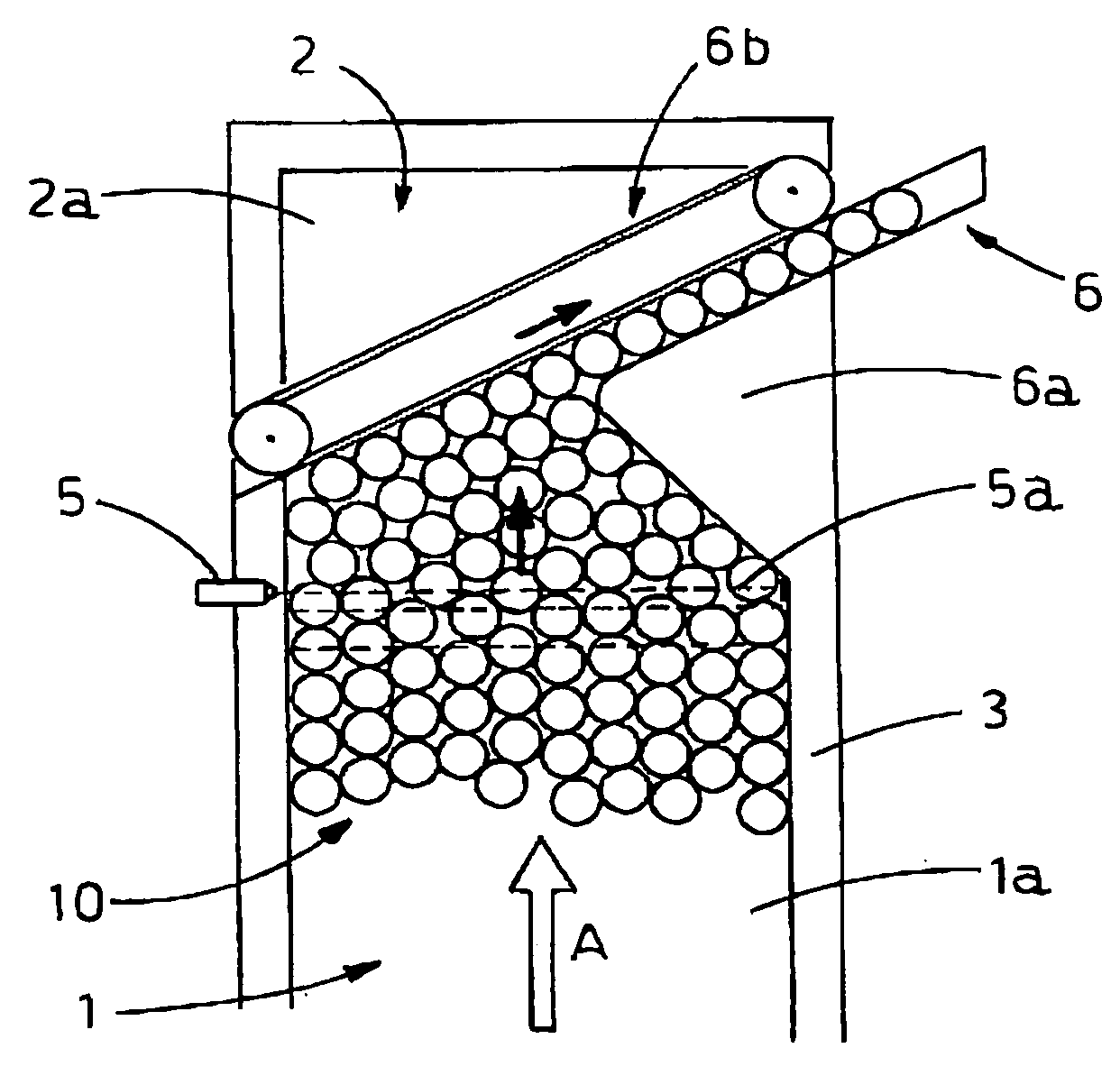
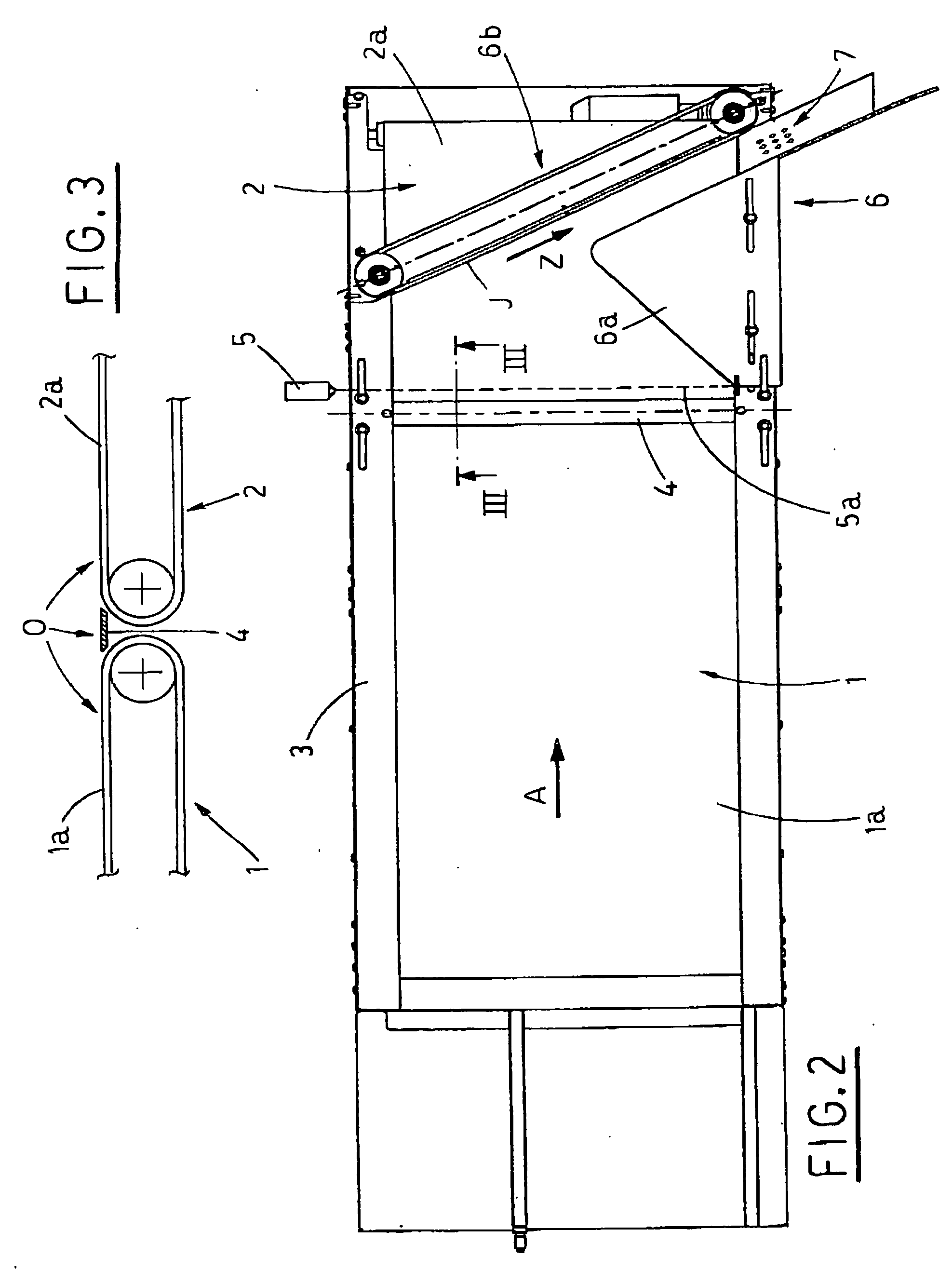
[0026] Having regards to the enclosed Figures, the reference numeral 3 indicates generally a stationary framework, which supports a first conveying belt 1 and a second conveying belt 2.

[0027] A spline 4, transversally interposed between the two conveyors and fastened to the framework 3, stabilizes the continuity of the upper runs 1a, 2a of the first conveying belt 1 and second conveying belt 2, respectively, and lies on the horizontal plane O defined by the runs 1a, 2a.

[0028] The first conveying belt 1 is operated as a consequence of the operation of first motor means, not shown, aimed at operating the relative upper run 1a in a feeding direction A, while the second conveying belt 2 is operated continuously (e.g. at constant speed), in a direction concordant with the feeding direction A, by the activation of second motor means, likewise not shown in Figures.

[0029] The reference numeral 5 indicates sensor means, e.g. optical, situated on one side of the upper run 2a and acting on ...


PUM


Abstract

A device for transporting and arranging cylindrical elements in a row has a first conveying belt, operated by first motor means to pull a plurality of cylindrical elements in a feeding direction. A second conveying belt is situated in cascade with respect to the first conveying belt and is operated continuously for receiving and transporting the plurality of cylindrical elements in a direction concordant with the feeding direction. Canalization means are fastened to an upper run of the second conveying belt for intercepting and for guiding the cylindrical elements, being transported on the second conveying belt, in a discharge direction up to an outlet channel, situated on one side thereof. Sensor means are connected with the first motor means and detect the presence of at least one cylindrical element in a selected section of the second conveying belt. The sensor means deactivate the first motor means, after a first time interval, subsequent to detection, and activate them, after a second time interval, when no cylindrical elements are detected in the selected section.

Description

FIELD OF THE INVENTION [0001] The present invention relates to means for transporting and canalizing, in particular in one row, cylindrical elements, such as bottles and the like. BACKGROUND OF THE INVENTION [0002] There are many applications, including different technical fields, which require the transport of cylindrical elements, full or empty, and their arrangement in a row, in order to perform a following processing step, e.g. filling the empty bottles and their subsequent closing. [0003] Known apparatuses include a first conveying belt, which pulls a plurality of bottles, placed on the corresponding upper run, from the inlet station toward the outlet station, near which canalization means canalize the bottles and arrange them in a row. [0004] With reference toFIG. 1, one of the known embodiments of the canalization means includes a first stationary abutment F1 and a second stationary abutment F2, having corresponding opposite areas, and a second conveying belt M, which has a r...

Claims


Application Information

Patent Timeline
IPC IPC(8): B65G47/12
CPCB65G47/682B65G2201/0244
Inventor MONTI, GIUSEPPE
Owner MARCHESINI GROUP SPA
Why Eureka
Try Eureka