Embeddable polarimetric fiber optic sensor and method for monitoring of structures

a fiber optic sensor and embedded technology, applied in the field of stress sensors, can solve the problems of not employing embedded sensors, using maintenance techniques and products that are more sophisticated and costly than they need, and affecting the use of applications and users

Active Publication Date: 2006-04-20
MORGAN RES CORP
View PDF18 Cites 29 Cited by
  • Summary
  • Abstract
  • Description
  • Claims
  • Application Information

AI Technical Summary

Benefits of technology

[0020] For purposes of summarizing the invention, certain aspects, advantages, and novel features of the invention have been described herein. It is to be understood that not necessarily all such advantages may be achieved in accordance with any one particular embodiment of the invention. Thus, the invention may be embodied or carried out in a manner that achieves or optimizes one advantage or group of advantages as taught herein without necessarily achieving other advantages as may be taught or suggested herein.

Problems solved by technology

Most current structures do not employ embedded sensors to aid in the determination of structural health.
These procedures result in excess cost to an application and the user as structures are replaced, repaired, and maintained more often than necessary, while also using maintenance techniques and products that are more sophisticated and costly than they need to be.
Three problems often exist with this approach to achieve a partial distributed sensor: multiple sites along the fiber must be prepared to write the FBGs, sites of interest on the structure must be predetermined and matched to the location of the gratings, and more sophisticated and expensive instrumentation is required to interrogate multiple FBGs.
These procedures can often restrict the type of environment that can implement a FBG or require a protective device that is not allowable in the structure to be monitored.
This removal of material drastically decreases the robustness of the sensor, which could limit its end application for use in hostile environments.

Method used


Image

  • Embeddable polarimetric fiber optic sensor and method for monitoring of structures
  • Embeddable polarimetric fiber optic sensor and method for monitoring of structures
  • Embeddable polarimetric fiber optic sensor and method for monitoring of structures

Examples


Embodiment Construction

[0031] The present invention and its advantages are best understood by referring to the drawings. The elements of the drawings are not necessarily to scale, emphasis instead being placed upon clearly illustrating the principles of the invention.

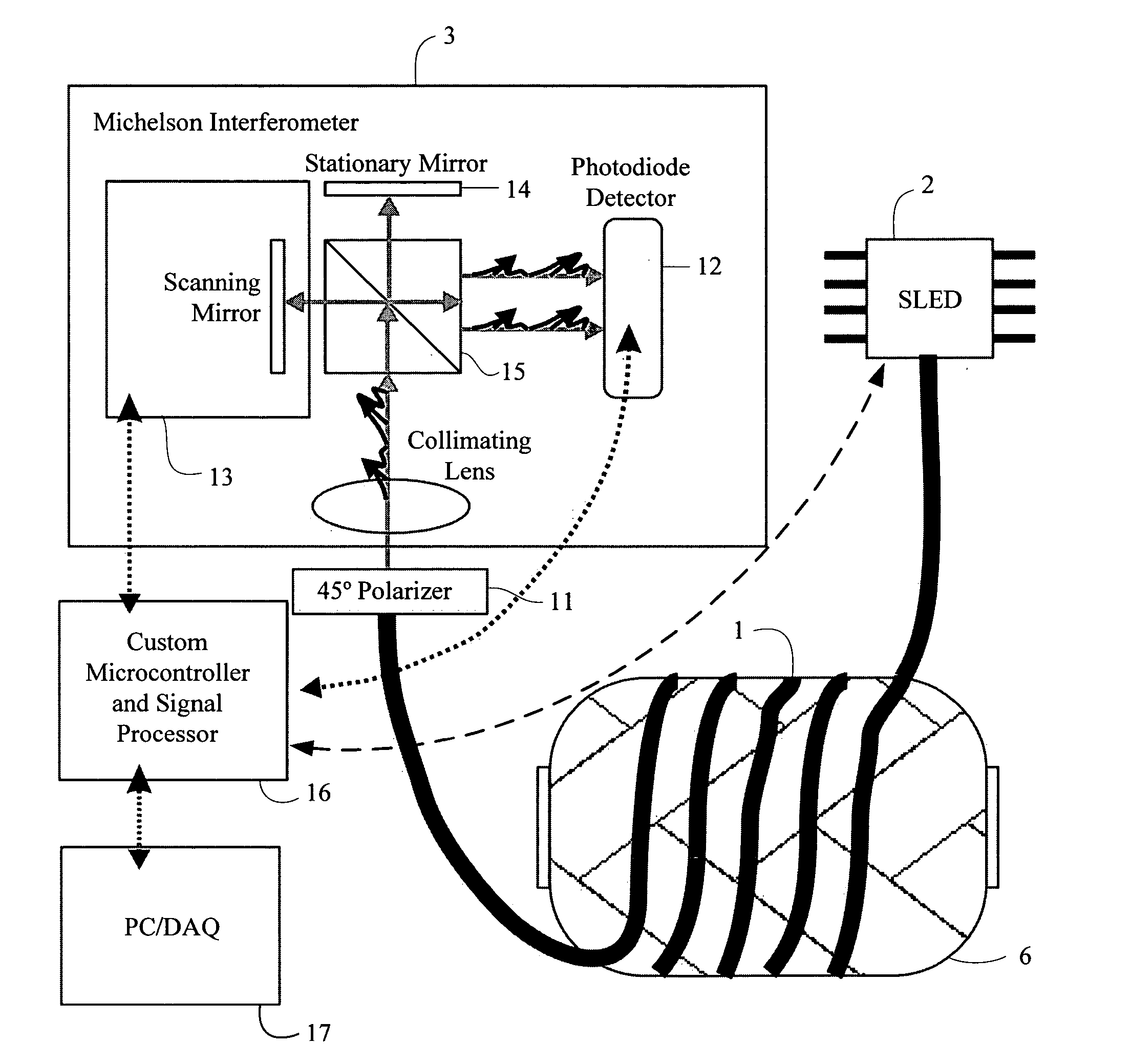
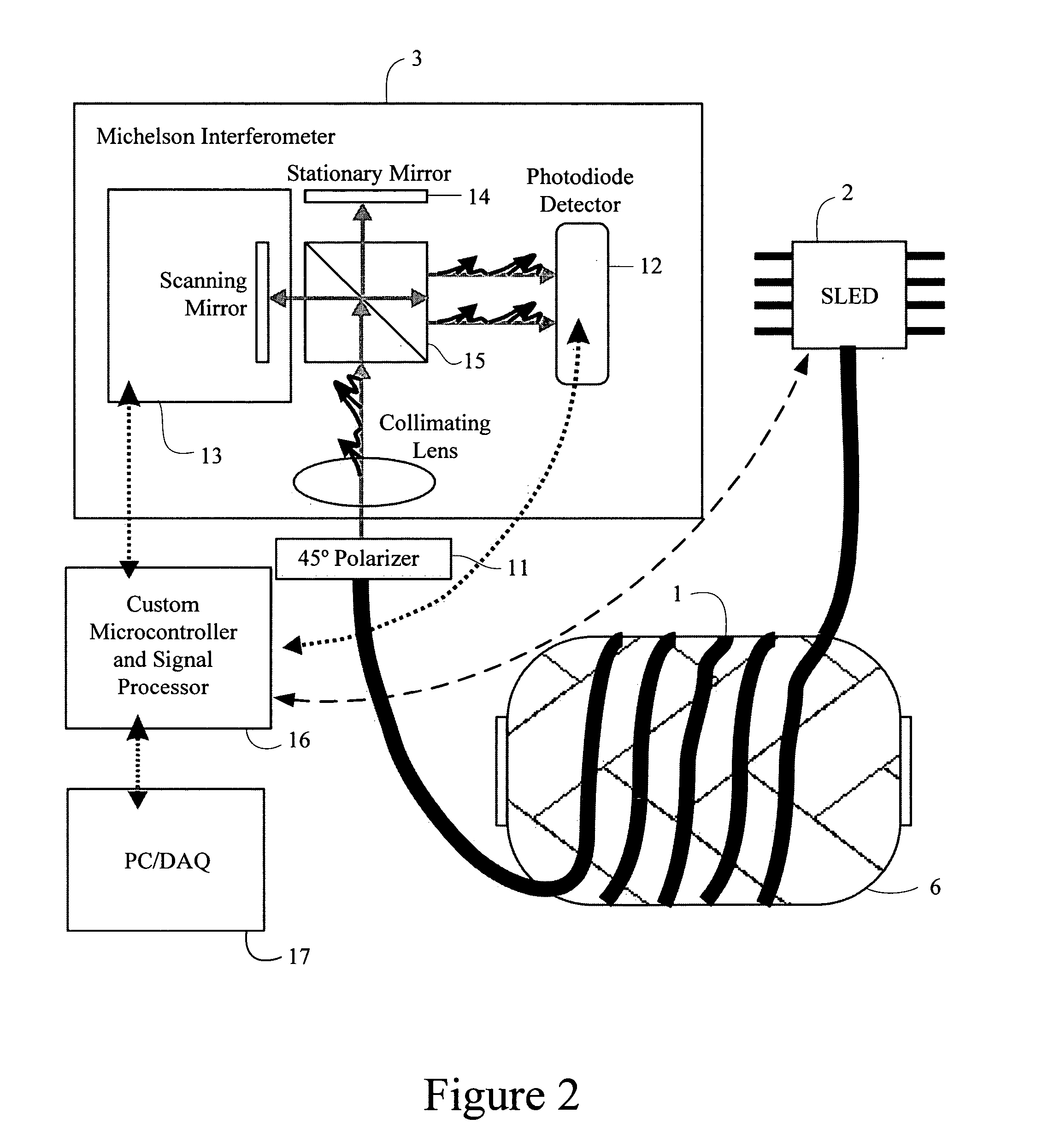
[0032] One embodiment of the invention is shown in FIG. 2. This embodiment uses a 30 mW 1565 nm super-luminescent light emitting diode (“SLED”) with a 3 dB bandwidth of 38 nm, resulting in a coherence length of 41 μm as the broadband optical source 2, although other optical sources could be used without departing from the scope of the invention. The output of the optical source 2 is polarized and aligned to one axis of the embedded fiber sensor 1. The fiber sensor 1 itself is a continuous length of polarization-maintaining single mode optical fiber wound around and embedded into the device under test 6. The fiber sensor 1 output is first transmitted through a polarizer 11 aligned at 45 degrees to the polarization axis of the fiber sensor 1. ...


PUM


Abstract

The present invention provides the capability of ascertaining, through a quick and simple measurement, locations on a structure that may have experienced damage that could result in reduced structure lifetime, strength, or reliability. The sensing element is a connectorized section of polarization maintaining (“PM”) optical fiber, where a length of PM fiber represents a fully distributed sensor array. Stress-induced changes to the sensor are measured through white-light Polarimetric interferometry. The output of the measurement is a data array representing the stress concentration magnitude at an array of locations along the length of the sensor. In an application, the knowledge of the optical fiber position on the structure, coupled with the measurement of stress locations along the fiber length, allows the user to determine locations on the structure with large stress concentrations. These locations may signify structural damage. This knowledge would allow the user to employ a more sophisticated system, albeit a larger and slower one, to fully characterize and evaluate that area of potential damage and take appropriate action.

Description

REFERENCE TO RELATED APPLICATIONS [0001] This application claims priority to Provisional Patent Application U.S. Ser. No. 60 / 619,419, entitled “Embeddable Polarimetric Fiber Optic Sensor and Method for Monitoring of Structures” and filed on Oct. 15, 2004, which is fully incorporated herein by reference.GOVERNMENT LICENSE RIGHTS [0002] This invention was made with Government support under contract number F33615-02-C-5013, awarded by the Missile Defense Agency. The Government has certain rights in the invention.BACKGROUND [0003] 1. Field of the Invention [0004] The present invention relates generally to a stress sensor. More particularly, the present invention relates to a fiber optic sensor that monitors stress on a structure. [0005] 2. Background of the Invention [0006] Embedding miniature sensors in structures, systems, storage and shipping containers, and other items allows the monitoring of these items to determine health, maintenance needs, lifetime, and other item characteristi...

Claims


Application Information

Patent Timeline
Patent Type & Authority Applications(United States)
IPC IPC(8): G01J1/04
CPCG01B11/161G01B11/168G01B11/18G01J3/453G01J4/00G01M11/085
Inventor WILLIAMS, JEFFERY LEEKRANZ, MICHAEL SCOTTHEATON, LARRY CHRISTOPHER
Owner MORGAN RES CORP
Why Eureka
Try Eureka