Motor control device

a technology of motor control and control device, which is applied in the direction of electric generator control, dynamo-electric converter control, dynamo-electric gear control, etc., can solve the problems of reduced efficiency of combined motor and inverter, and limited operation speed, so as to reduce the input current and minimize the input current of the inverter. , the effect of improving the robustness of the automatic weakening flux control against the temperature change of th

Active Publication Date: 2019-11-05
MITSUBISHI ELECTRIC CORP
View PDF6 Cites 0 Cited by
  • Summary
  • Abstract
  • Description
  • Claims
  • Application Information

AI Technical Summary

Benefits of technology

[0025]FIG. 8 is a graph showing the effect of the present invention when the motor temperature decreases. According to the present invention, during automatic weakening flux control, the current motor temperature is detected, the magnet flux of the motor corresponding to the motor temperature is calculated by the magnet flux calculating section, by updating the center point of the voltage limit ellipse using the calculated magnet magnetic flux of the motor, an appropriate voltage limit ellipse 801 and a center point 802 of an appropriate voltage limit ellipse can be obtained. Therefore, when the current vector 805 is input as the command value at the beginning, the current vector is corrected towards the point 802 and reaches the intersection point 901 with the voltage limiting ellipse 801 according to the automatic weakening flux control. Further, the robustness of the automatic weakening flux control against the temperature change of the motor is improved. Further, when the d-q axis current command value reaches the point 901, a constant torque curve at the intersection point 901 is calculated as a combination candidate of the d-q axis current which minimizes the input current of the inverter, the d axis coordinate of the point 901 is compared with the d axis coordinate of the point 802, when the d axis coordinate of the point 901 is large, it is arranged in the negative d axis direction, when the d axis coordinate of the point 901 is small, a d-q axis current that minimizes the input current of the inverter within the combination candidate of the d-q axis current is searched in the positive d axis direction, by correcting the current command value at the point 903 where the efficiency becomes the maximum, it is possible to alleviate a decrease in system efficiency comprising the motor and the inverter according to the automatic weakening flux control. In addition, even when the motor temperature rises, the same effect can be obtained by the present invention.

Problems solved by technology

In the case of driving a permanent magnet type synchronous motor, if the attempt is made to rotate at high speed, as the induced voltage becomes higher than the maximum voltage that the inverter can output, and the generator operates, the operation speed is limited.
However, with this method, when the motor temperature changes from the designed value, since the characteristics of the motor change, when the current command value is corrected, the combination of the d-q axis currents is not optimal with respect to the torque and the number of revolutions, there is a problem that the efficiency of the motor decreases and the efficiency of the combined motor and inverter decreases.

Method used


Image

  • Motor control device
  • Motor control device
  • Motor control device

Examples


first embodiment

[0037]Hereinafter, a preferred embodiment 1 of a motor control device according to the present invention will be described with reference to FIGS. 1 to 8. In the respective drawings, the same or corresponding parts will be described with the same reference numerals.

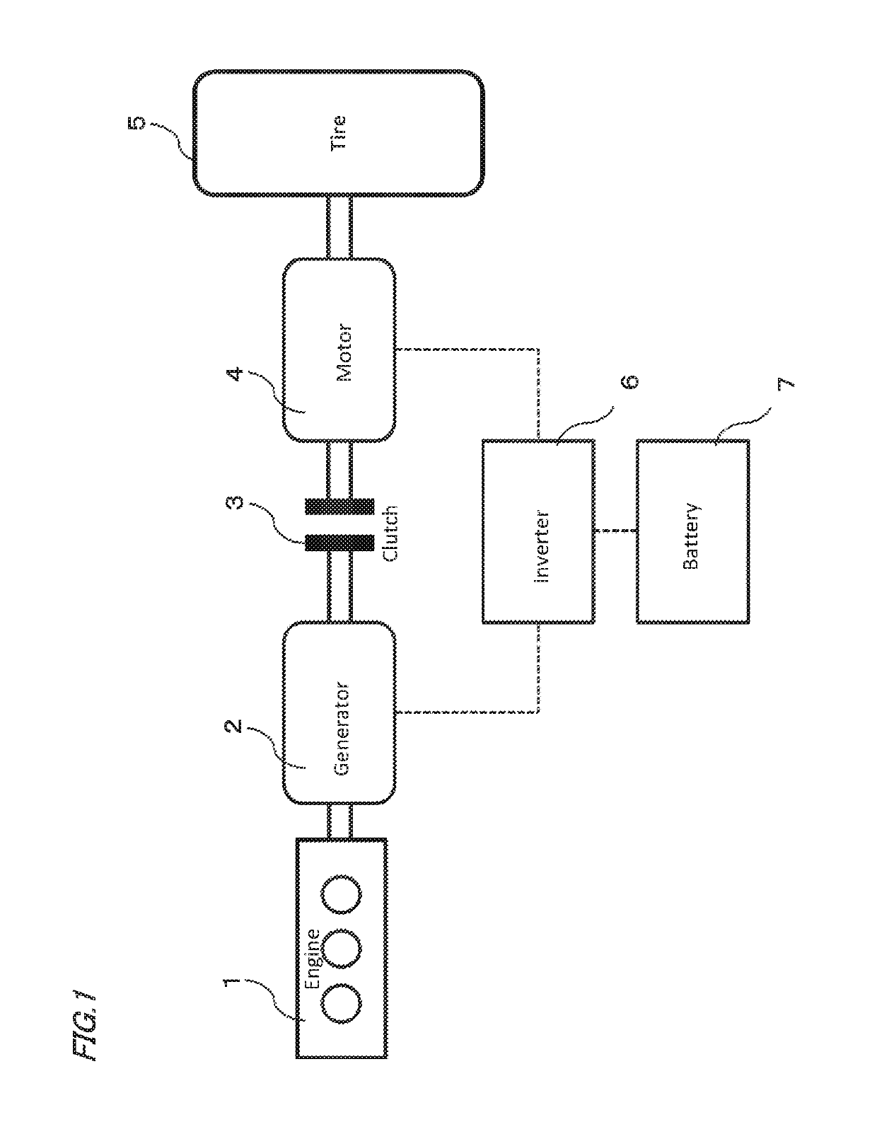
[0038]FIG. 1 is a schematic configuration diagram showing a vehicle in which a motor control device is mounted according to a first embodiment of the present invention. In FIG. 1, a hybrid vehicle including the engine 1 and the motor 4 is described as an example, but the present embodiment is also applicable to an electric vehicle. In FIG. 1, a generator 2 is driven by an engine 1, so that a generator 2 generates electric power, and the generated electric power is charged into a battery 7 via an inverter 6.

[0039]Then, the motor 4 is driven by supplying electric power generated by the generator 2 or electric power stored in the battery 7 to the motor 4. The motor 4 drives the tire 5 to run the vehicle. When supplying the e...


PUM


Abstract

A motor control device having a motor temperature sensor for detecting a magnet temperature of the motor, a magnet magnetic flux calculation section that calculates a magnet magnetic flux of the motor corresponding to the magnet temperature of the motor, a current combination candidate calculating section that calculates a d-q axis current combination candidate that minimizes the input current of the inverter within a voltage limit ellipse determined by a value that can be output by a voltage of a power supply of the motor, and a d-q axis current search section that searches the d-q axis current that minimizes the input current of the inverter within the range of the combination candidate of the d-q axis currents when the d-q axis current of the motor moves on a voltage limiting ellipse by automatic weakening flux control.

Description

CROSS REFERENCE TO RELATED APPLICATIONS[0001]This application is a National Stage of International Application No. PCT / JP2015 / 067825 filed Jun. 22, 2015, the contents of which are incorporated herein by reference in its entirety.TECHNICAL FIELD[0002]The invention relates to a motor control device, and more particularly to a motor control device that alleviates a reduction in system efficiency when a weakening magnetic flux control is performed.BACKGROUND ART[0003]In recent years, hybrid vehicles and electric vehicles have attracted attention as energy saving and environmental conscious vehicles. Hybrid vehicles use motors as power sources in addition to conventional engines, and electric vehicles use motors as power sources.[0004]Both the hybrid vehicle and the electric vehicle convert DC power stored in a battery into AC power by an inverter circuit and supply the power to the motor to run the vehicle.[0005]Hereinafter, the configuration and operation of the control device of a con...

Claims


Application Information

Patent Timeline
Patent Type & Authority Patents(United States)
IPC IPC(8): H02P21/22H02P29/66B60L15/02H02P21/00H02P21/14H02P6/17
CPCH02P21/22H02P21/141B60L15/025H02P21/0089H02P29/662B60L2240/425H02P6/17B60L2240/429B60L2240/529Y02T10/64
Inventor HARADA, SHINGOENOKI, KEIICHIMURATA, YASUKAZUWATANABE, MASUTAKANISHIJIMA, YOSHIMASA
Owner MITSUBISHI ELECTRIC CORP
Why Eureka
Try Eureka