Variable noise control for an optical transducer

a technology of optical transducers and variable noise, applied in the field of variable noise control of optical transducers, can solve the problems of increasing the risk of erroneous signal transitions in the ir receiver, increasing the risk of ir receivers, and increasing the number of optical transducers, so as to achieve noise control and reduce the irradiance of optical transducers

Active Publication Date: 2006-04-20
LITE ON TECH CORP
View PDF8 Cites 14 Cited by
  • Summary
  • Abstract
  • Description
  • Claims
  • Application Information

AI Technical Summary

Benefits of technology

[0006] In yet another embodiment, as optical irradiance of an optical transducer decreases, the gain of one or more amplifier stages receiving an output of the

Problems solved by technology

However, when configured for maximum gain, IR receivers become increasingly susceptible to erroneous signal transitions as a result of power supply noise.
Poor PSRR performance by an IR receiver may result in a phenomenon known as “dark bits,” which are unwanted

Method used


Image

  • Variable noise control for an optical transducer
  • Variable noise control for an optical transducer
  • Variable noise control for an optical transducer

Examples


Embodiment Construction

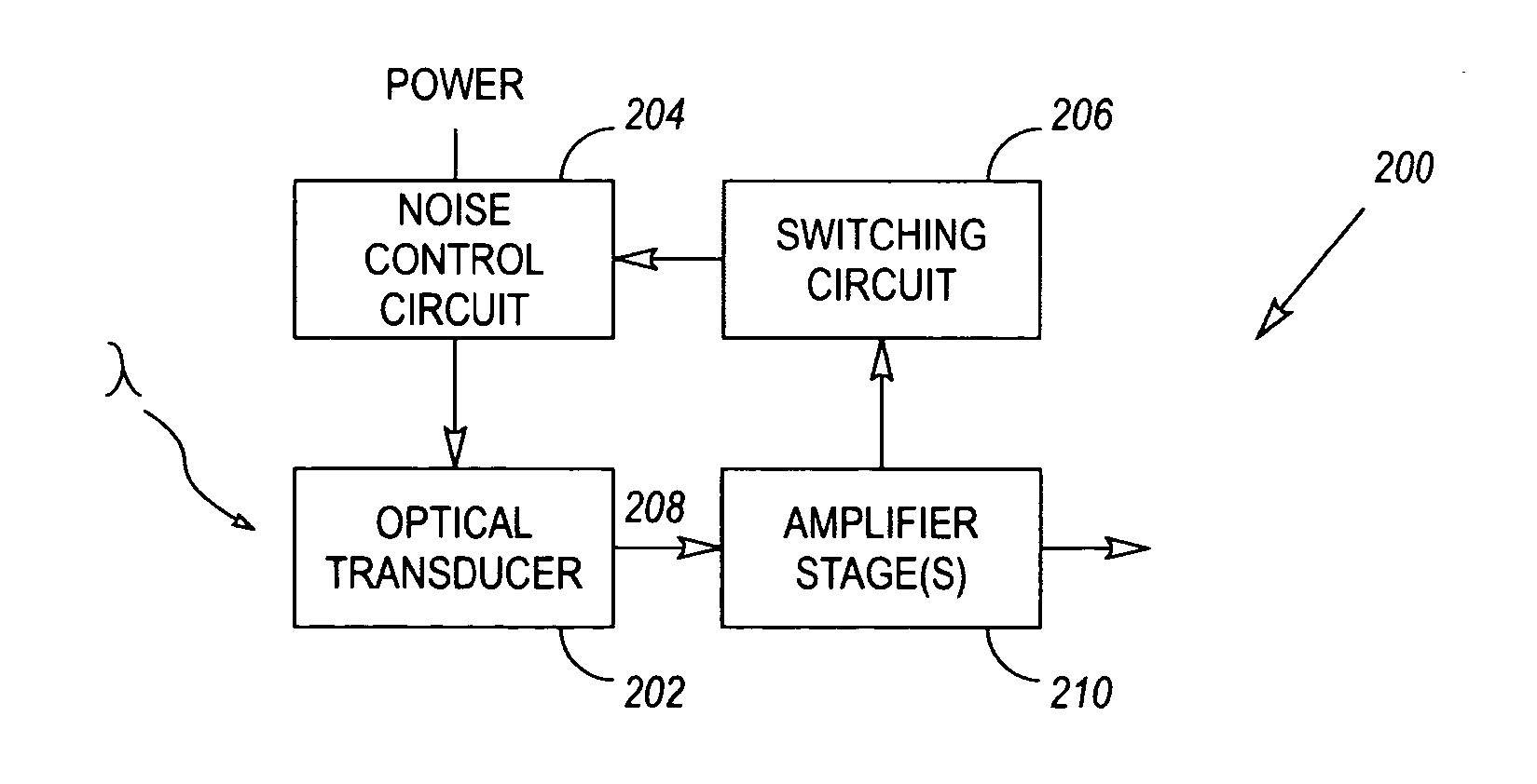
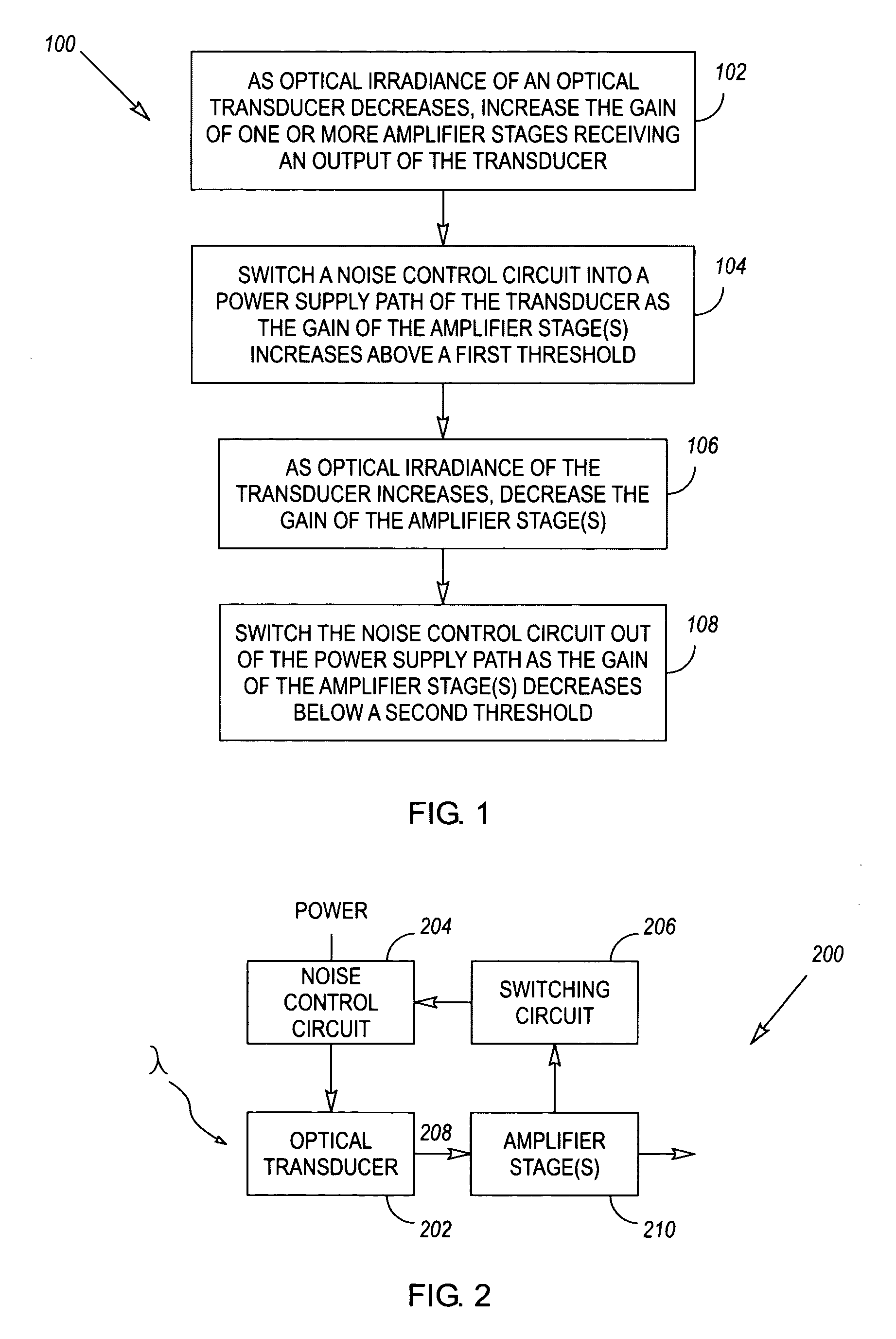
[0017]FIG. 1 illustrates a first exemplary method 100 for varying the noise control provided to an optical transducer. By way of example, the optical transducer may take the form of an infrared (IR) transducer that is designed to convert optical signals received from an IR transmitter into electrical signals.

[0018] In accordance with the method 100, as optical irradiance of the transducer decreases, the gain of one or more amplifier stages that receive an output of the transducer is increased 102. When the gain of the amplifier stage(s) increases above a first threshold, a noise control circuit is switched into 104 a power supply path of the transducer. As optical irradiance of the transducer increases, the gain of the one or more amplifier stages is decreased 106. When the gain of the amplifier stage(s) decreases below a second threshold, the noise control circuit is switched out 108 of the power supply path. The first and second thresholds may be the same or different.

[0019] Und...


PUM


Abstract

In one embodiment, an optical transducer, such as an infrared transducer, generates an output signal that is representative of optical irradiance. A noise control circuit is coupled in a power supply path of the optical transducer. A switching circuit varies the noise control provided by the noise control circuit, in response to changes in the output signal of the optical transducer. The noise control may be varied in a number of different ways, including: turning the noise control on or off, varying the noise control in discrete steps, or varying the noise control in a continuous manner. Methods for varying noise control in response to optical irradiance of an optical transducer are also disclosed.

Description

BACKGROUND [0001] Wireless infrared data communications are standardized by the Infrared Data Association (IrDA) in a series of published specifications. IrDA specifications support a wide range of data rates (i.e., from 9.6 kbps to 16 Mbps) in three data rate modes (i.e., SIR or Serial Infrared up to 115.2 kbps, FIR or Fast Infrared up to 4 Mbps, and VFIR or Very Fast Infrared up to 16 Mbps). IrDA supports a wide range of radiant signal intensities at the output of wireless transmitters, 3.6 to 500 mW / sr in two power modes (i.e. low and standard). IrDA also supports communication distances from zero to one meter. [0002] In view of the wide-ranging data rates, signal intensities, and transmission distances supported by IrDA, IR receivers must accommodate a wide dynamic range of inputs over a wide frequency bandwidth. This may be accomplished, in part, using variable gain amplification. In the case of minimal irradiance, IR receivers must be configured for maximum gain in order to id...

Claims


Application Information

Patent Timeline
IPC IPC(8): G01J5/00H04B10/11H04B10/112H04B10/118H04B10/2507
CPCH04B10/58H01L31/02016H04B1/1018
Inventor YEO, KOK-SOONXU, LIAN-CHUNTEO, CHEE-KEONGASUNCION, JOHN JULIUS DE LEON
Owner LITE ON TECH CORP
Why Eureka
Try Eureka