Dipolar side-emitting LED lens and LED module incorporating the same

a technology of led modules and led lenses, applied in the field of diodes (led), can solve the problems of reducing the color uniformity of an entire lcd backlight module, obstructing the miniaturization of lcd backlights, and poor uniformity

Active Publication Date: 2006-04-20
SAMSUNG ELECTRONICS CO LTD
View PDF2 Cites 139 Cited by
  • Summary
  • Abstract
  • Description
  • Claims
  • Application Information

AI Technical Summary

Benefits of technology

[0013] The present invention has been made to solve the foregoing problems of the prior art, and it is therefore an object of the present invention to provide a dipolar LED and an LED module incorporating the same, by which when light be

Problems solved by technology

Then, the LEDs are necessarily increased in number corresponding to the light loss by the blocked areas BA10, thereby obstructing the miniaturization of the LCD backlight.
However, light beams L2 generated in the periphery of the LED chip 2a are out of total reflection condition and thus emitted upward without refl

Method used


Image

  • Dipolar side-emitting LED lens and LED module incorporating the same
  • Dipolar side-emitting LED lens and LED module incorporating the same
  • Dipolar side-emitting LED lens and LED module incorporating the same

Examples


Embodiment Construction

[0045] Preferred embodiments of the present invention will now be described in more detail with reference to the accompanying drawings.

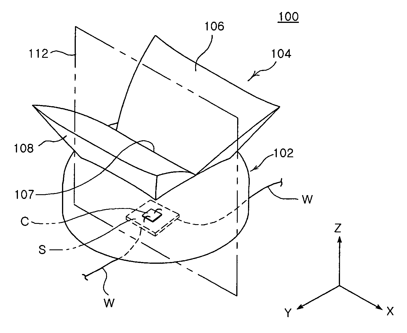
[0046]FIG. 4 is a perspective view of an LED lens according to a first embodiment of the invention, FIG. 5 is a perspective view of the LED lens shown in FIG. 4 which is arranged in a different orientation, FIG. 6 is a plan view of the LED lens shown in FIG. 4, FIG. 7 is a front elevation view of the LED lens shown in FIG. 4, and FIG. 8 is a side elevation view of the LED shown in FIG. 4.

[0047] Referring FIGS. 4 to 8, an LED lens 100 of the invention comprises a unitary body made of transparent material, and includes an upper hemisphere-shaped base 102 and a pair of opposite wings 104 projected from opposite top portions of the base 102.

[0048] The base 102 is generally shaped as a hemisphere to receive an LED chip C therein while radiating light generated by the LED chip C to the outside.

[0049] The wings 104 are configured symmetric about an imag...


PUM


Abstract

The present invention relates to a dipolar LED and a dipolar LED module incorporating the same, in which an upper hemisphere-shaped base houses an LED chip therein and adapted to radiate light from the LED chip to the outside, and a pair of reflecting surfaces placed at opposed top portions of the base in a configuration symmetric about an imaginary vertical plane. The vertical plane passes through the center of the LED chip perpendicularly to a light-emitting surface of the LED chip. The reflecting surfaces are extended upward away from the top portions of the base to reflect light from the LED chip away from the imaginary vertical plane. A pair of radiating surfaces are placed outside the reflecting surfaces, respectively, to radiate light from the reflecting surfaces to the outside. In this way, light emission from the LED chip can be concentrated in both lateral directions.

Description

RELATED APPLICATION [0001] The present application is based on, and claims priority from, Korean Application Number 2004-84120, filed Oct. 20, 2004, the disclosure of which is hereby incorporated by reference herein in its entirety. BACKGROUND OF THE INVENTION [0002] 1. Field of the Invention [0003] The present invention relates to a Light Emitting Diode (LED), and more particularly, to a dipolar LED structured to concentrate light emission in both lateral directions and an LED module incorporating the same. [0004] 2. Description of the Related Art [0005] According to the development of electronic devices, Liquid Crystal Displays are gaining attention as next generation display devices. Since an LCD does not light spontaneously, it is required to provide a backlight unit for generating light in rear of an LCD panel. [0006]FIG. 1 is a cross-sectional view illustrating a Light Emitting Diode (LED) lens disclosed in U.S. Pat. No. 6,679,621 as an example of a conventional side-emitting ...

Claims


Application Information

Patent Timeline
IPC IPC(8): H01L33/00H01L33/54H01L33/56
CPCH01L33/54H01L33/60
Inventor KIM, JIN HAHAHM, HUN JOOKIM, HYUNG SUKKIM, JIN JONGJUN, JOO HEELEE, SANG HYUCKKYONG, CHON SUJEONG, HO SEOP
Owner SAMSUNG ELECTRONICS CO LTD
Why Eureka
Try Eureka