
Image processor, image processing method, and image processing program product

Inactive Publication Date: 2006-04-20
NEC ELECTRONICS CORP
View PDF1 Cites 9 Cited by
  • Summary
  • Abstract
  • Description
  • Claims
  • Application Information

AI Technical Summary

Benefits of technology

[0010] According to the image processor, the shaded space can be represented as boundary data in the same form as the object data, making it possible to reflect the brightness of the shaded space in a display image through the same processing as object rendering without any special hardware implantation, suppress a calculation amount, and improve an image quality.
[0012] According to the image processing method, the shaded space can be represented as boundary data in the same form as the object data, making it possible to reflect the brightness of the shaded space in a display image through the same processing as object rendering without any special hardware implantation, suppress a calculation amount, and improve an image quality.
[0014] According to the image processing program product, the shaded space can be represented as boundary data in the same form as the object data, making it possible to reflect the brightness of the shaded space in a display image through the same processing as object rendering without any special hardware implantation, suppress a calculation amount, and improve an image quality.
[0015] According to the present invention, it is possible to provide an image processor, an image processing method, and an image processing program, none of which require special implantation in hardware, or installation of a program requiring a larger calculation amount.

Problems solved by technology

This method can precisely shade the object, but has a problem that a shaded portion in the space is not taken into consideration.
However, a problem arises that such a method requires special hardware, thereby increasing costs.
Further, if this method is implemented by software, a special processing is required, which means a larger calculation amount, resulting in high load on a processor.

Method used


Image

  • Image processor, image processing method, and image processing program product
  • Image processor, image processing method, and image processing program product
  • Image processor, image processing method, and image processing program product

Examples


Embodiment Construction

[0029] The invention will be now described herein with reference to illustrative embodiments. Those skilled in the art will recognize that many alternative embodiments can be accomplished using the teachings of the present invention and that the invention is not limited to the embodiments illustrated for explanatory purposed.

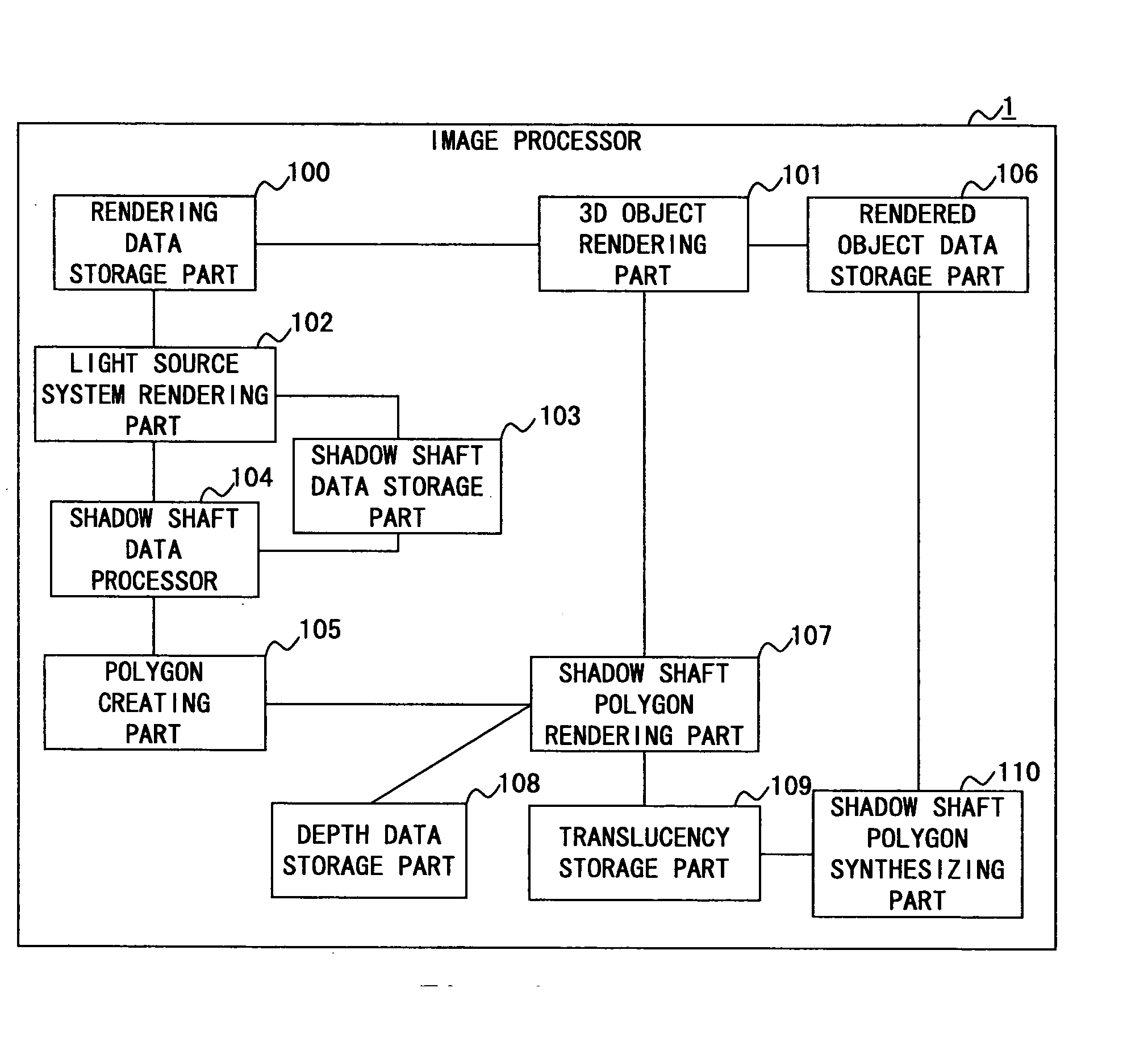
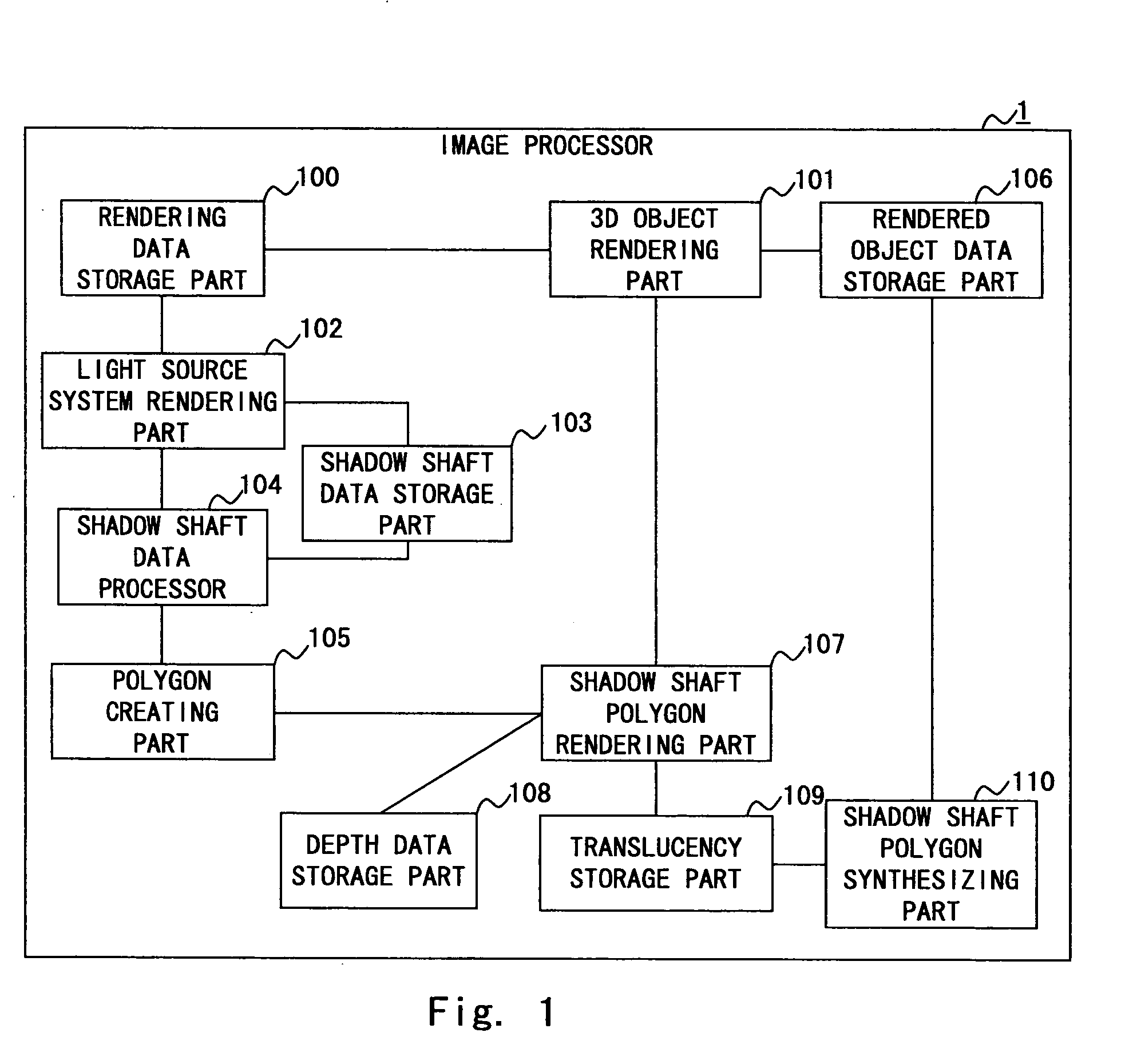
[0030]FIG. 1 is a block diagram showing the configuration of an image processor according to an embodiment of the present invention. An image processor 1 is implementable by means of a program in a computer-readable medium. The image processor 1 may be incorporated in, for example, PC (personal computer), a cell phone, or other special devices. The image processor 1 includes a rendering data storage part 100, a 3D object rendering part 101, a light source system rendering part 102, a shadow shaft data storage part 103, a shadow shaft data processor 104, a polygon creating part 105, a rendered object data storage part 106, a shadow shaft polygon rendering part 1...


PUM


Abstract

To provide an image processor, an image processing method, and an image processing program, none of which require special hardware implementation and installation of a program requiring a large calculation amount. An embodiment of the present invention relates to an image processor for representing a shaded space defined by an object in a 3D space blocking light from a light source, which generates boundary data including positional information on the light source and positional information on the object to calculate the brightness of the shaded space based on the generated boundary data. With such a structure, the shaded space can be represented as boundary data in the same form as the object data, making it possible to reflect the brightness of the shaded space in a display image through the same processing as object rendering without any special hardware implantation, suppress a calculation amount, and improve an image quality.

Description

BACKGROUND OF THE INVENTION [0001] 1. Field of the Invention [0002] The present invention relates to an image processor, an image processing method, and an image processing program product, and more particularly to an image processor, image processing method, and image processing program product for displaying a 3D image. [0003] 2. Description of Related Art [0004] In the field of 3D computer graphics, there have been a variety of shading techniques based on information on a light source and an object. Among those, a typical one is a Z buffer method. [0005] The Z buffer method is such that information about the distance from a view point to a display target is stored in a memory area called a Z buffer, and if some objects overlap, their distances are compared with reference to the Z buffer to display the object nearest to the view point on the screen. The Z buffer method requires more memory area for the Z buffer. However, because of its simple algorithm, the Z buffer method is easi...

Claims


Application Information

Patent Timeline
IPC IPC(8): G06T15/50G06T15/60
CPCG06T15/40G06T15/60
Inventor OHBUCHI, EISAKU
Owner NEC ELECTRONICS CORP
Learn More