Device and system for in vivo imaging

a technology imaging device, which is applied in the field of in vivo imaging device and system, can solve the problems of high bandwidth input transmitter for video signals and low power, and achieve the effect of improving the accuracy of in vivo imaging results

Inactive Publication Date: 2006-04-20
GIVEN IMAGING LTD
View PDF72 Cites 42 Cited by
  • Summary
  • Abstract
  • Description
  • Claims
  • Application Information

AI Technical Summary

Benefits of technology

[0008] Further, the imaging system may utilize a white light emitting diode (LED) as a light source rather than a reddish incandescence miniature bulb or an RGB LED presently used in the art. The white LED enables to produce a higher quality and more pleasant to the eye image.
[0021] The NO switch is controlled by an external magnet that keeps the switch closed while it is in proximity to the switch. However, an internal block maintains the logistics of an open switch, so as to keep the transmitter circuits and all capsule main subsystems inactive while the external magnet is present. Removal of the external magnet causes the switch to open and the internal block to close, thereby allowing the transmitter circuits and capsule main subsystems to be activated.

Problems solved by technology

Further, an ultra low power, high bandwidth input transmitter for video signals is unknown in the art.

Method used


Image

  • Device and system for in vivo imaging
  • Device and system for in vivo imaging
  • Device and system for in vivo imaging

Examples


Embodiment Construction

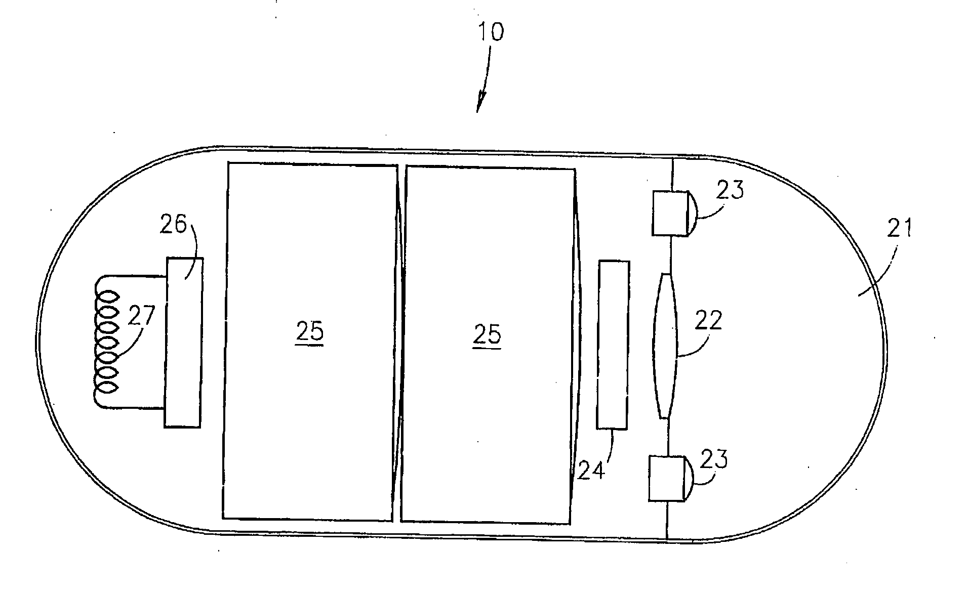
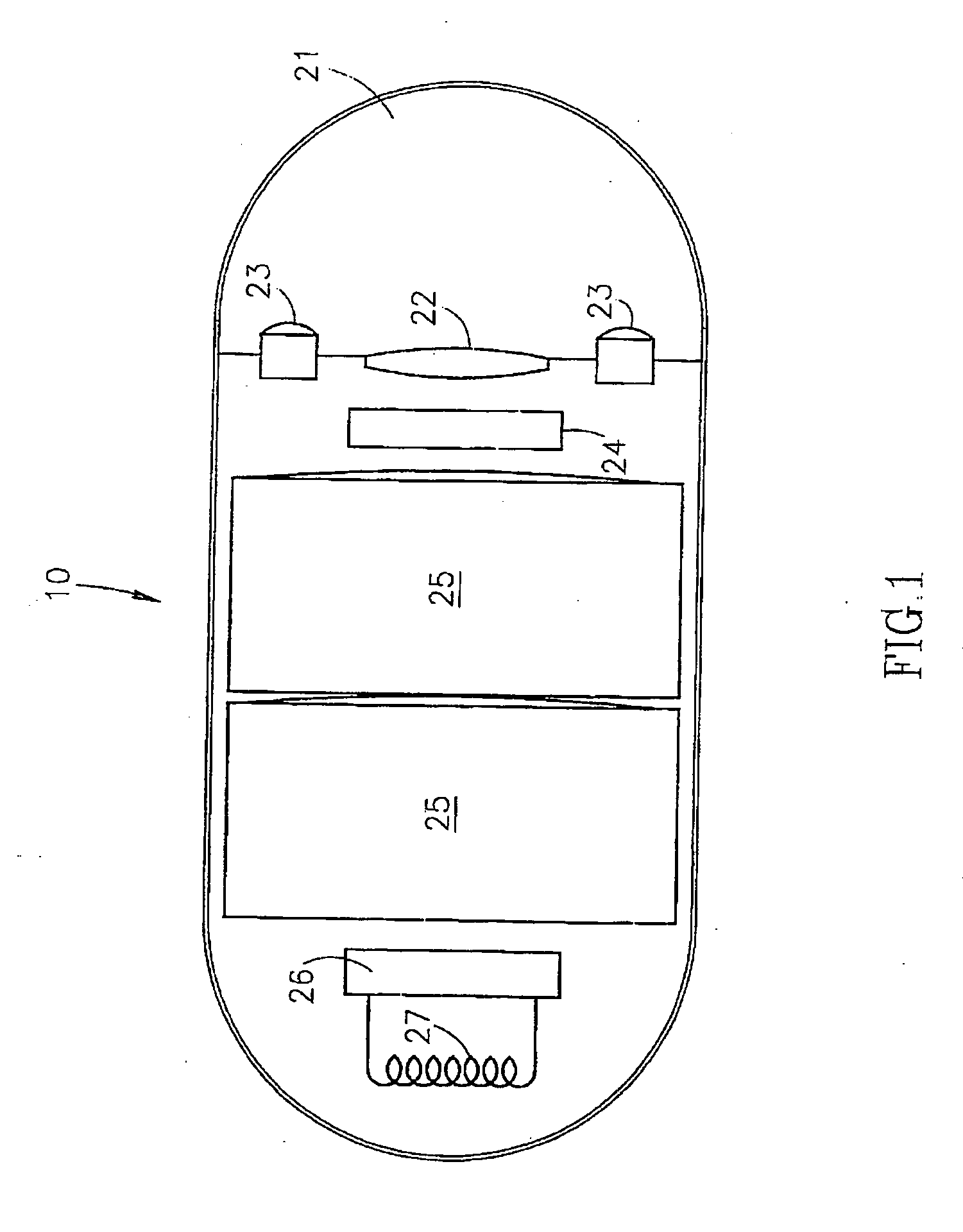
[0029] The device and system of the invention are utilized for viewing inside body lumens and cavities and for transmitting at least video data.

[0030] Reference is now made to FIG. 1 which illustrates the device and its components, according to an embodiment of the invention The device 10 typically comprises an optical window 21 and an imaging system for obtaining images from inside a body lumen, such as the GI tract. The imaging system includes an illumination source 23, such as a white LED, a CMOS imaging camera 24, which detects the images and an optical system 22 which focuses the images onto the CMOS imaging camera 24. The illumination source 23 illuminates the inner portions of the body lumen through optical window 21. Device 10 further includes a transmitter 26 and an antenna 27 for transmitting the video signal of the CMOS imaging camera 24, and a power source 25, such as a silver oxide battery, that provides power to the electrical elements of the device 10.

[0031] It will...


PUM


Abstract

The present invention provides a system and method for obtaining in vivo images. The system contains an imaging system and a transmitter for transmitting signals from a camera to a receiving system located outside a patient.

Description

PRIOR APPLICATION DATA [0001] This application is a continuation of prior application Ser. No. 09 / 800,470, filed on Mar. 8, 2001, entitled “A DEVICE AND SYSTEM FOR IN VIVO IMAGING” which in turn claims priority from prior U.S. provisional application 60 / 187,883, filed on Mar. 8, 2000, entitled “IN-VIVO IMAGING DEVICE AND SYSTEM”, each of which being incorporated by reference herein in their entirety.FIELD OF THE INVENTION [0002] The present invention relates to an in vivo imaging device and system such as for imaging the digestive tract. BACKGROUND OF THE INVENTION [0003] Among known in vivo measuring systems are endoscopes, which are often utilized to provide images of the upper or lower gastro-intestinal tract. However, endoscopes do not provide views of the entire length of the small intestines. Additionally, they are uncomfortable, may cause damage to the patient and are complex to operate. [0004] Swallowable electronic capsules which are moved through the digestive tract throug...

Claims


Application Information

Patent Timeline
Patent Type & Authority Applications(United States)
IPC IPC(8): A61B1/04H04N7/18A62B1/04H04N9/47A61B1/00G03B15/00A61B1/05A61B1/273A61B1/31A61B5/00A61B5/07G03B15/02H04L25/03H04N5/225
CPCA61B1/00016A61B1/00032A61B1/00036A61B1/041A61B1/0607A61B1/0676A61B1/0684A61B1/2733A61B1/2736A61B1/31A61B5/0031A61B5/073A61B5/14539A61B2560/0209H04L25/03866H04N5/2251H04N5/2252H04N5/2256H04N5/23203H04N7/185H04N2005/2255H04N23/51H04N23/56H04N23/555H04N23/66H04N23/50A61B1/0016
Inventor IDDAN, GAVRIEL J.AVNI, DOVGLUKHOVSKY, ARKADYMERON, GAVRIEL
Owner GIVEN IMAGING LTD
Why Eureka
Try Eureka