Exposure method, exposure apparatus, and method for producing device

a technology of exposure apparatus and substrate surface, which is applied in the direction of photomechanical apparatus, printers, instruments, etc., can solve the problems of insufficient margin and difficulty in matching the substrate surface with respect to the image plane of the projection optical system, and achieve the desired performance and satisfactory pattern transfer accuracy

Inactive Publication Date: 2006-04-20
NIKON CORP
View PDF91 Cites 98 Cited by
  • Summary
  • Abstract
  • Description
  • Claims
  • Application Information

AI Technical Summary

Benefits of technology

[0057] According to a twelfth aspect of the present invention, there is provided a method for producing a device, comprising using the exposure method as defined above. According to a thirteenth aspect of the present invention, there is provided a method for producing a ...

Problems solved by technology

If the depth of focus δ is too narrowed, it is difficult to match the substrate surface with respect to the image plane of the projection optical system.
It is feared that the margin is insufficient during the exposure operation.
When a temperature distribution arises in the liquid, th...

Method used


Image

  • Exposure method, exposure apparatus, and method for producing device
  • Exposure method, exposure apparatus, and method for producing device
  • Exposure method, exposure apparatus, and method for producing device

Examples


first embodiment

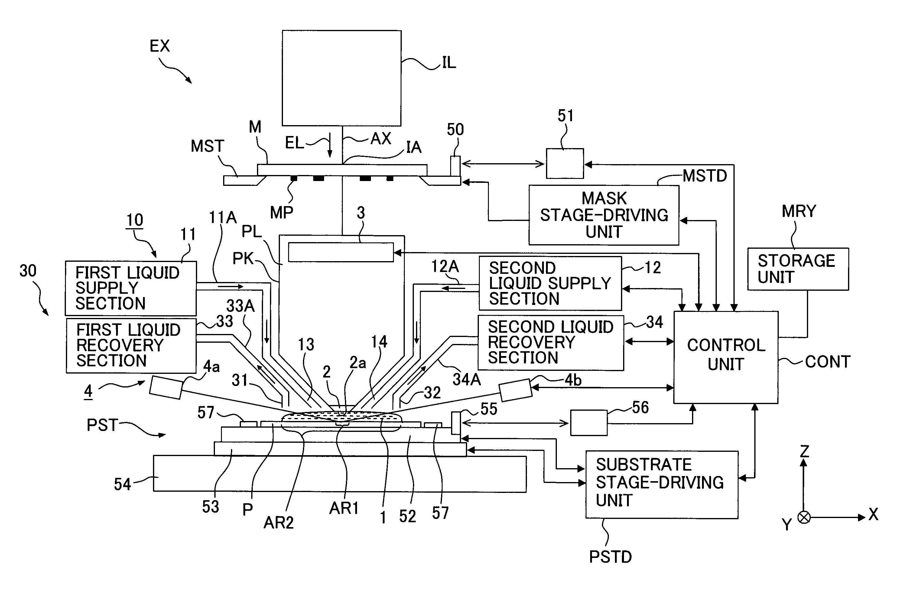
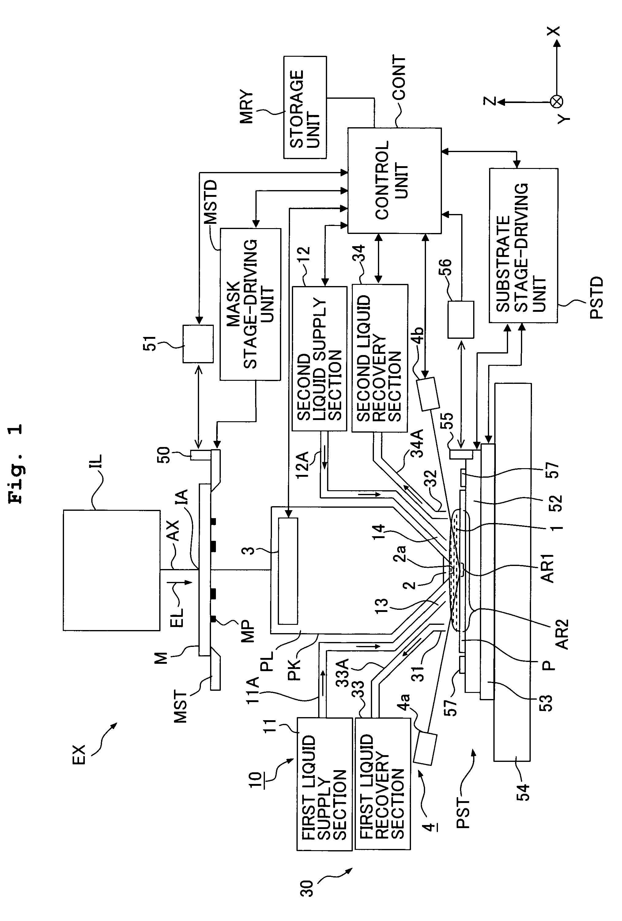
[0075]FIG. 1 shows a schematic arrangement illustrating a first embodiment of the exposure apparatus of the present invention. With reference to FIG. 1, an exposure apparatus EX principally includes a mask stage MST which supports a mask M, a substrate stage PST which supports a substrate P, an illumination optical system IL which illuminates, with an exposure light beam EL, the mask M supported by the mask stage MST, a projection optical system PL which performs projection exposure for the substrate P supported by the substrate stage PST with an image of a pattern of the mask M illuminated with the exposure light beam EL, a control unit CONT which collectively controls the overall operation of the exposure apparatus EX, and a storage unit MRY which is connected to the control unit CONT and which stores various pieces of information about the exposure operation including information about the distribution of the pattern MP of the mask M.

[0076] The exposure apparatus EX of this embo...

second embodiment

[0128] Next, an explanation will be made about a second embodiment of the exposure apparatus of the present invention with reference to FIG. 10. In this embodiment, the projection state is adjusted by making the adjustment so that any temperature distribution is not generated in the liquid 1 of the liquid immersion area AR2 depending on the pattern distribution of the mask M (distribution of the exposure light beam EL which comes into the projection area AR1), i.e., so that the temperature distribution of the liquid 1 is uniformized. In particular, the adjustment is made so that the temperature distribution is uniform in the Y axis direction as the direction perpendicular to the scanning direction (X axis direction). This embodiment is constructed in the same manner as the first embodiment except for the liquid supply mechanism. In the following explanation, the constitutive portions, which are the same as or equivalent to those of the first embodiment described above, are designate...

third embodiment

[0139] Next, an explanation will be made with reference to FIG. 11 about a third embodiment of the exposure apparatus EX of the present invention. In this embodiment, the liquid supply mechanism and the liquid recovery mechanism are changed as follows. As shown in FIG. 11, the exposure apparatus EX includes a liquid supply mechanism 10 which has two supply tubes 71, 72 (supply ports 71A, 72A) provided and aligned in the Z axis direction as the direction perpendicular to the X axis direction, and a liquid recovery mechanism 30 which has two recovery tubes 73, 74 (recovery ports 74A, 74A) provided and aligned in the Z axis direction so that the recovery tubes 73, 74 are opposed to the supply tubes 71, 72. The liquid supply mechanism 10 is capable of supplying the liquid from the respective supply ports 71A, 72A at mutually different temperatures. Accordingly, two liquid layers LQ1, LQ2, which have temperatures different from each other, can be formed in the liquid immersion area AR2. ...


PUM


Abstract

An exposure method forms an immersion area in at least a part of a substrate including a projection area of a projection optical system and projects an image of a mask pattern onto the substrate through liquid between the projection optical system and the substrate. Distribution of the mask pattern is measured (S1) and adjustment is made so that a desired image of the pattern is projected onto the substrate according to distribution of the exposure light incident into the liquid between the projection optical system and the substrate when exposing the substrate (S4 to S6). It is possible to expose the substrate with the pattern accurately regardless of the distribution of the mask pattern.

Description

CROSS-REFERENCE [0001] This application is a Continuation Application of International Application No. PCT / JP2004 / 007569 which was filed on May 26, 2004 claiming the conventional priority of Japanese patent Application No. 2003-151369 filed on May 28, 2003.BACKGROUND OF THE INVENTION [0002] 1. Field of the Invention [0003] The present invention relates to an exposure method, an exposure apparatus, and a method for producing a device wherein a substrate is exposed with a pattern in a state in which a liquid immersion area is formed between a projection optical system and the substrate. [0004] 2. Description of the Related Art [0005] Semiconductor devices and liquid crystal display devices are produced by means of the so-called photolithography technique in which a pattern formed on a mask is transferred onto a photosensitive substrate. The exposure apparatus, which is used in the photolithography step, includes a mask stage for supporting the mask and a substrate stage for supporting...

Claims


Application Information

Patent Timeline
IPC IPC(8): G03B27/52G03F7/20
CPCG03F7/70258G03F7/70341G03F7/70858G03F7/7085G03F7/70433G03F7/2041H01L21/0274G03F7/70875G03F7/70891
Inventor HIRUKAWA, SHIGERU
Owner NIKON CORP
Why Eureka
Try Eureka