
MIMO communication system using an adaptive transmission mode switching technique

a communication system and adaptive transmission technology, applied in multiplex communication, wireless communication, wireless communication, etc., can solve the problems of insufficient increase in transmission bandwidth alone. , to achieve the effect of increasing spectral efficiency

Active Publication Date: 2006-04-20
SAMSUNG ELECTRONICS CO LTD +1
View PDF7 Cites 102 Cited by
  • Summary
  • Abstract
  • Description
  • Claims
  • Application Information

AI Technical Summary

Benefits of technology

[0015] It is, therefore, an aspect of the present invention to provide a multiple-input multiple-output (MIMO) communication system and method that increase the spectral efficiency for a predefined target error rate by performing adaptive transmission mode switching using a novel switching criterion.

Problems solved by technology

However, because the CDMA transmission scheme has limitations in processing large-capacity wireless data, a multicarrier based orthogonal frequency division multiplexing (OFDM) transmission scheme is being considered for next generation wireless communication systems.
However, an increase in the transmission bandwidth alone is not sufficient to satisfy a target transmission rate for the next generation wireless communication systems.
Although, multiple-input multiple-output (MIMO) multiplexing scheme for increasing a transmission rate using multiple antennas is difficult to be applied for wideband transmission.
An increase in the transmission bandwidth alone is not sufficient to satisfy a target transmission rate for fourth generation (4G) wireless communication systems.
However, the spatial selectivity of a channel is not considered in the link adaptation algorithm.
However, this transmission mode switching technique may obtain significant diversity gain, but is based on a fixed transmission rate.

Method used


Image

  • MIMO communication system using an adaptive transmission mode switching technique
  • MIMO communication system using an adaptive transmission mode switching technique
  • MIMO communication system using an adaptive transmission mode switching technique

Examples


Embodiment Construction

[0023] Preferred embodiments in accordance with the present invention will be described in detail herein below with reference to the accompanying drawings. In the following description of the present invention, a detailed description of known functions and configuration incorporated herein will be omitted when it may obscure the subject matter of the present invention.

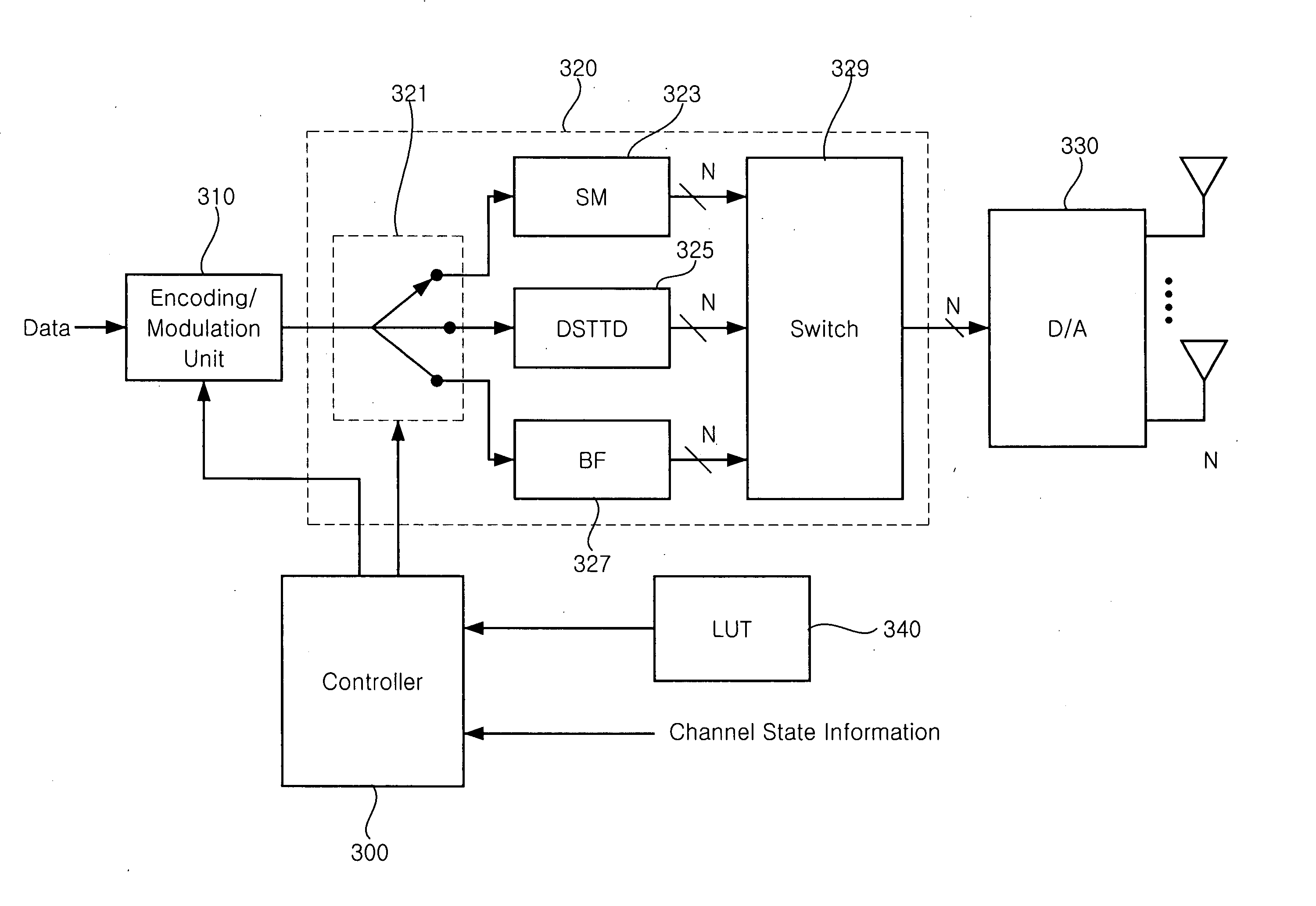
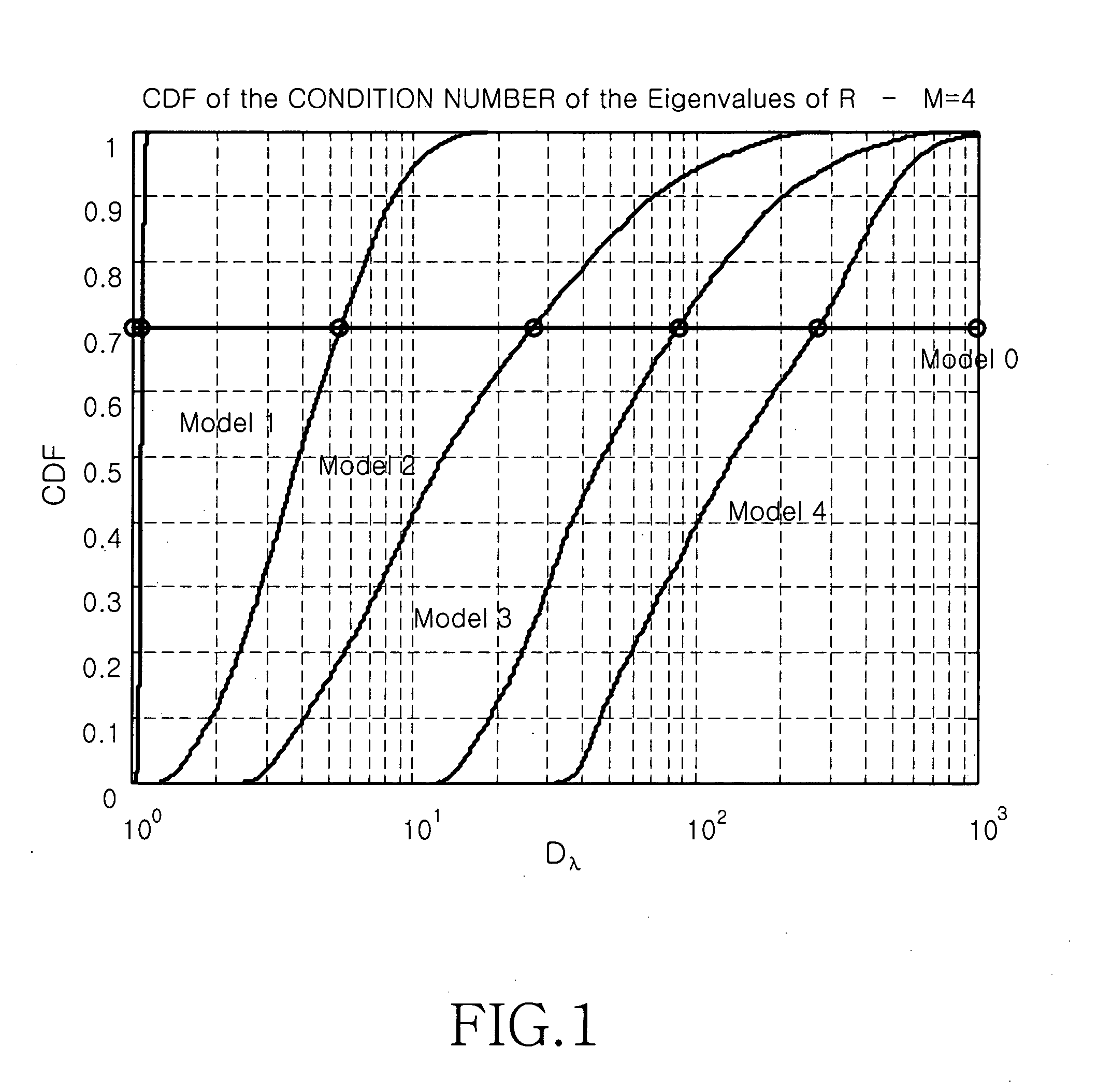
[0024] In accordance with the present invention, the adaptive transmission mode switching method introduces a new switching criterion to increase the spectral efficiency for a predefined target error rate. The adaptive transmission mode switching method characterizes channel spatial selectivity based on a metric derived from spatial correlation matrices.

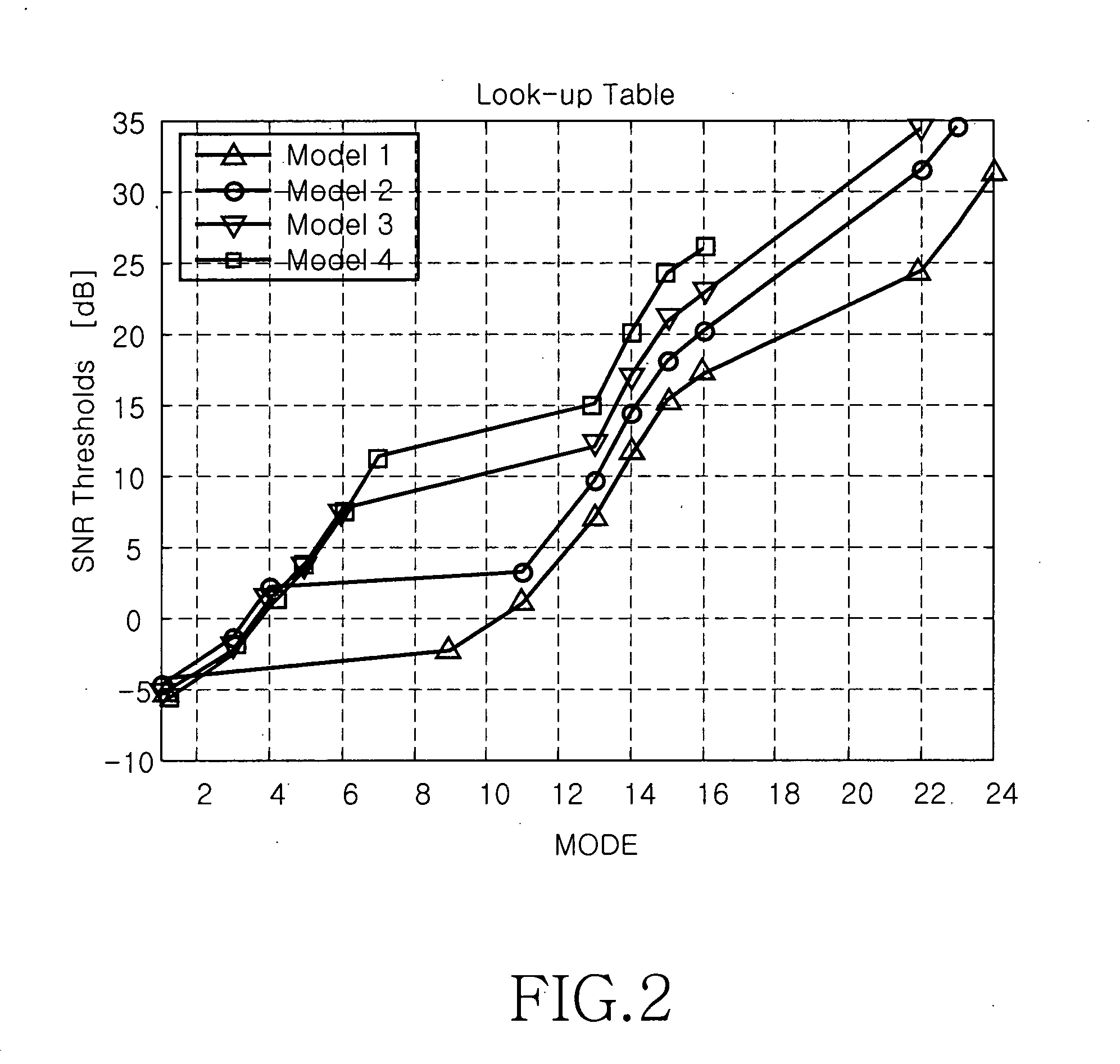
[0025] In accordance with the present invention, the adaptive transmission mode switching method estimates channel quality and adaptively selects a MIMO transmission scheme that maximizes the throughput for a given error rate and transmit power on the basis of the est...


PUM


Abstract

A multiple-input multiple-output (MIMO) wireless communication system. A transmitter that includes a plurality of transmit antennas selects one of a spatial multiplexing scheme and a spatial diversity scheme, processes a signal in the selected transmission scheme, and transmits the signal through the plurality of transmit antennas. A receiver that includes a plurality of receive antennas processes a signal in a reception scheme mapped to a transmission scheme of the transmitter. The transmission schemes include a transmission scheme for maximizing diversity gain and a transmission scheme for maximizing spectral efficiency. The MIMO communication system using an adaptive transmission mode switching technique performs switching between MIMO transmission modes using spatial selectivity of a channel, thereby obtaining maximum gain in a signal to noise ratio (SNR) and spectral efficiency according to channel state.

Description

PRIORITY [0001] This application claims priority under 35 U.S.C. § 119 to a provisional application entitled “MIMO Communication System Using Adaptive Transmission Mode Switching Technique” filed in the United States Patent and Trademark Office on Sep. 7, 2004 and assigned Ser. No. 60 / 607,738, and to an application entitled “MIMO Communication System Using Adaptive Transmission Mode Switching Technique” filed in the Korean Intellectual Property Office on Dec. 29, 2004 and assigned Serial No. 2004-115347, the contents of both of which are incorporated herein by reference.BACKGROUND OF THE INVENTION [0002] 1. Field of the Invention [0003] The present invention relates generally to multiple-input multiple-output (MIMO) communication systems, and more particularly to a MIMO communication system for selecting an optimal MIMO transmission and reception scheme and communicating using the selected scheme. [0004] 2. Discussion of the Related Art [0005] Recent wireless communication technolog...

Claims


Application Information

Patent Timeline
IPC IPC(8): H04J9/00
CPCH04B7/0689H04J9/00H04L1/0001
Inventor FORENZA, ANTONIOHEATH, ROBERT W.PARK, HYOUNG-WOONYANG, HOKIM, HO-JINKOUNTOURIS, MARIOSASHISH, PANDHARIPANDE
Owner SAMSUNG ELECTRONICS CO LTD
Learn More