Multimode wavelength multiplexing optical transceiver

Inactive Publication Date: 2006-04-20
HITACHI CABLE
View PDF14 Cites 39 Cited by
  • Summary
  • Abstract
  • Description
  • Claims
  • Application Information

AI Technical Summary

Benefits of technology

[0019] It is an object of the invention to provide a multimode wavelength multiplexing optical tran

Problems solved by technology

The reason to reduce the low-order mode component is that, when the other wavelength multiplexing optical transceiver receives a multimode light through the MMF transmission line, a differential mode delay is caused by the low-order mode component, thereby increasing a bit error rate when a digital signal carried on the light is decoded.
This troubles a worker to connect the mode-conditioning patch cord, necessitates securing the mode-conditioning patch cord or a connector thereof by some member, and

Method used


Image

  • Multimode wavelength multiplexing optical transceiver
  • Multimode wavelength multiplexing optical transceiver
  • Multimode wavelength multiplexing optical transceiver

Examples


first embodiment

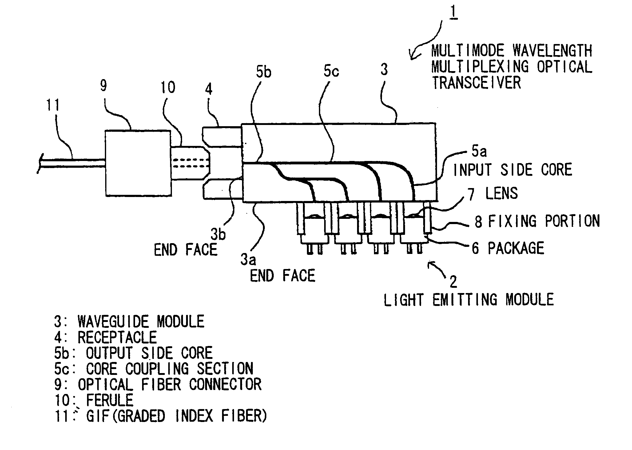
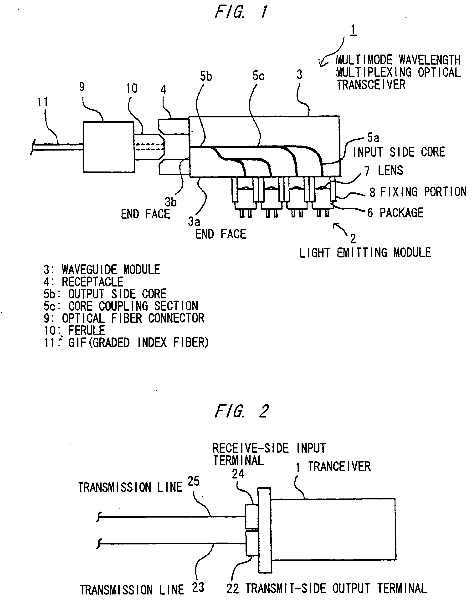
[0046]FIG. 1 is a schematic diagram showing a multimode wavelength multiplexing optical transceiver in the first preferred embodiment according to the invention.

[0047] As shown, the multimode wavelength multiplexing optical transceiver (hereinafter simply called transceiver) 1 comprises: plural light emitting modules 2 that light emitting elements to output single-mode lights with wavelengths different each other is sealed in a package with a lens; the step-index type multimode waveguide module 3 that guides and multiplexes lights from the light emitting modules and allows the reduction of the low-order mode component in generating a multimode light; and an optical fiber connector receptacle (hereinafter simply called receptacle) 4 that is provided at an output terminal for outputting the multiplexed multimode light from the step-index type multimode waveguide module 3.

[0048] The transceiver 1 is provided with a component for reception, but the component is omitted herein. Further...

second embodiment

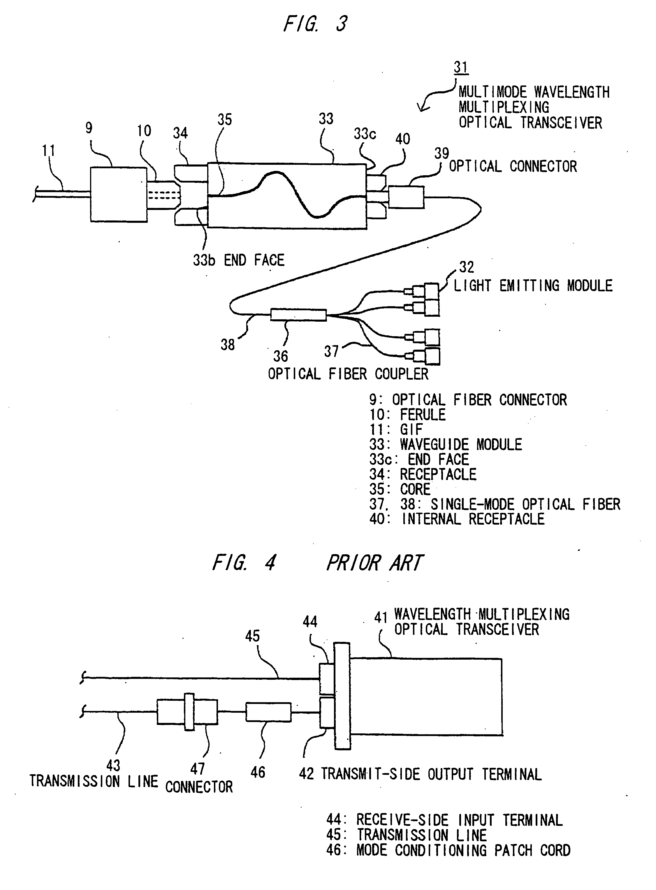
[0059]FIG. 3 is a schematic diagram showing a multimode wavelength multiplexing optical transceiver in the second preferred embodiment according to the invention.

[0060] As shown, the multimode wavelength multiplexing optical transceiver (hereinafter simply called transceiver) 31 comprises: plural light emitting modules 2 that light emitting elements to output single-mode lights with wavelengths different each other is sealed in a package with an optical fiber; a single-mode optical fiber coupler (hereinafter simply called optical fiber coupler) 36 to multiplex lights from the light emitting modules 2; a waveguide module 33 that has a core 35 with a core diameter of 25 μm square, guides and multiplexes lights from the light emitting modules, and allows the reduction of the low-order mode component in generating a multimode light; and a receptacle 4 that outputs the multiplexed multimode light from the waveguide module 33.

[0061] The light emitting module 32 is of so-called a pig tal...


PUM


Abstract

A multimode wavelength multiplexing optical transceiver has: a plurality of light emitting elements that emit single-mode lights with wavelengths different from each other; and a multimode waveguide module that is operable to multiplex the emitted single-mode lights into a multimode light. The multimode waveguide module is a step-index type multimode waveguide module that is operable to reduce a low-order mode component of the multimode light.

Description

[0001] The present application is based on Japanese patent application No. 2005-013924, the entire contents of which are incorporated herein by reference. BACKGROUND OF THE INVENTION [0002] 1. Field of the Invention [0003] This invention relates to a multimode wavelength multiplexing optical transceiver that MMF can be used as a transmission line and, particularly, to a multimode wavelength multiplexing optical transceiver that can reduce a low-order mode component without using any mode conditioning path cord. [0004] 2. Description of the Related Art [0005] In general, in a wavelength multiplexing optical transceiver for transmitting / receiving a wavelength-multiplexed light, a single-mode optical fiber (SMF) is connected to its transmit-side output terminal and an SMF or a multimode optical fiber (MMF) is connected to its receive-side input terminal. The reason to connect the SMF to the transmit-side output terminal is that a single-mode light is output from the transmit-side outpu...

Claims


Application Information

Patent Timeline
IPC IPC(8): G02B6/26G02B6/28
CPCG02B6/1228G02B6/29344G02B6/2938G02B6/4206G02B6/4292
Inventor TAKAHASHI, RYUTAHIRANO, KOKI
Owner HITACHI CABLE
Why Eureka
Try Eureka