Heat shield

a heat shield and shielding technology, applied in the field of heat shields, can solve the problems of difficult to shape stainless steel to such necessary contours, severe force acting on the heat shield, and copper is not very suitable for isolation, so as to prevent the formation of eddy currents, avoid thermal stresses, and save weigh

Inactive Publication Date: 2006-04-20
MAX PLANCK GESELLSCHAFT ZUR FOERDERUNG DER WISSENSCHAFTEN EV +2
View PDF14 Cites 20 Cited by
  • Summary
  • Abstract
  • Description
  • Claims
  • Application Information

AI Technical Summary

Problems solved by technology

However, copper is not very suitable for isolation of powerful superconductive solenoid coils since the solenoid coils induce eddy currents in the copper, which cause severe forces acting on the heat shield.
However, it is difficult to shape stainless steel to such necessary contours, and a copper shield cannot be used, or can be used only with limitations, owing to the strong magnetic fields.
The electrical conductivity in the transverse direction remains virtually zero, however, nevertheless, particularly when using glass fibre materials, thus preventing eddy currents.
Heat shields which are subject to particularly severe loads may, however, also have a thickness of several centimetres.

Method used


Image

  • Heat shield
  • Heat shield

Examples


Embodiment Construction

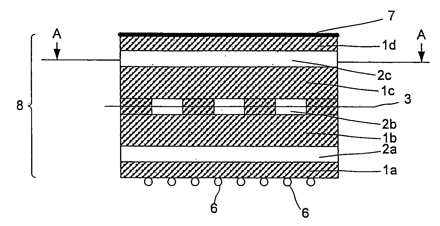
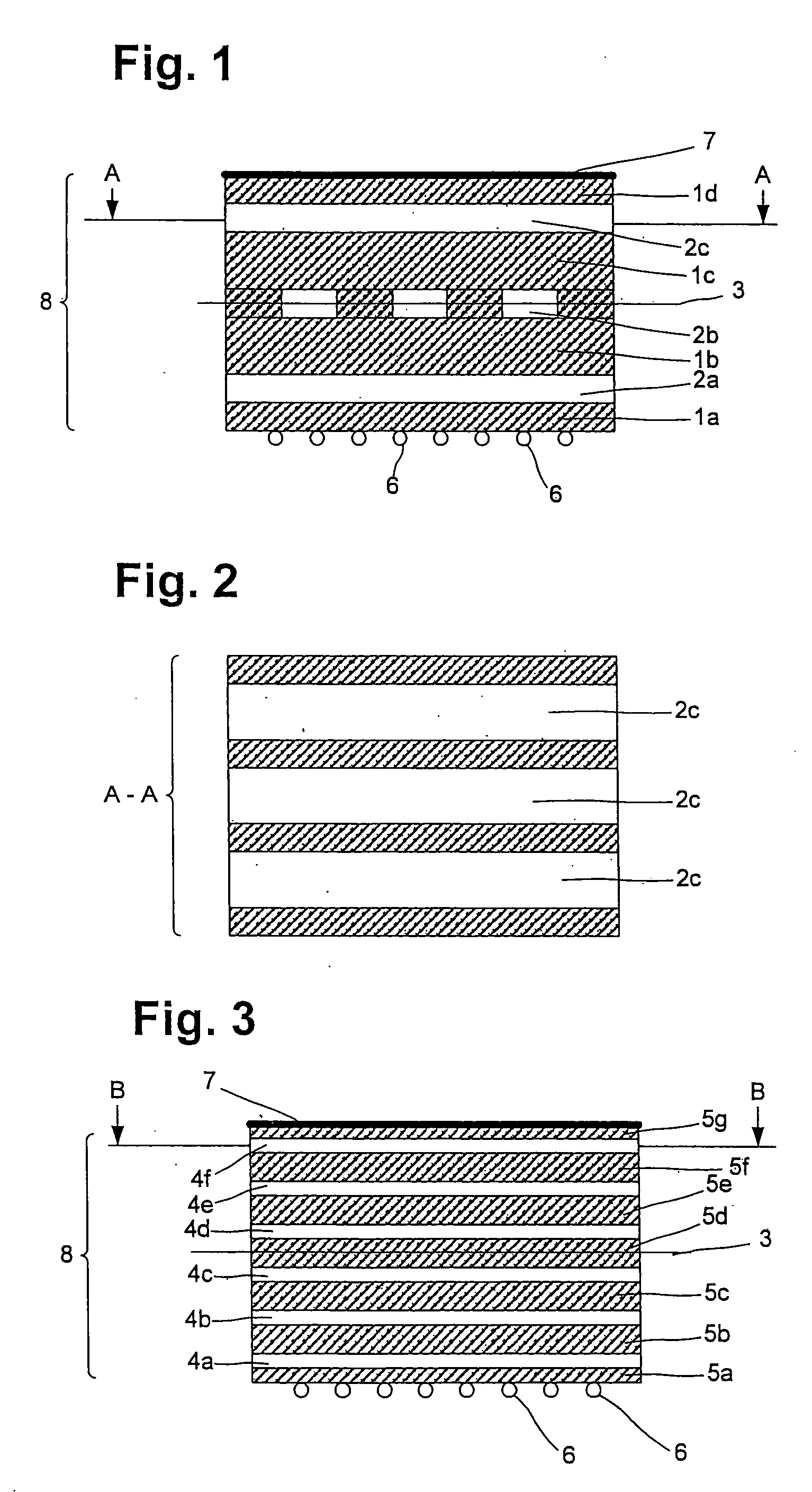
[0030]FIG. 1 shows a section through a part of a heat shield in accordance with an embodiment of the present invention. The illustrated part represents a detail from the entire heat shield. The body 8 of the heat shield is produced from two or more layers 1a, 1b, 1c, 1d of a glass fibre mesh. Narrow strips 2a, 2b, 2c of a copper sheet are placed between the layers 1a, 1b, 1c, 1d. The strips 2a and 2c run essentially parallel to one another while, in contrast, the central copper strips 2b are arranged at right angles to the sheet-metal strips 2a, 2c and at right angles to the plane of the drawing. Two or more of the copper strips are arranged parallel to one another on a plane at right angles to the plane of the drawing. This is shown by the example of the plane A-A in FIG. 2. The entire arrangement is constructed symmetrically with respect to the plane 3 which runs at right angles to the plane of the drawing.

[0031] Instead of the metal strips 2a, 2b, 2c illustrated in FIG. 1, it is...


PUM

PropertyMeasurementUnit
thicknessaaaaaaaaaa
thicknessaaaaaaaaaa
thicknessaaaaaaaaaa

Abstract

A heat shield having a thermally conductive body. The material of the body is composed of a fibre composite material, preferably carbon fibre, glass fibre, glass-fibre-reinforced plastic and / or aramide, and layers of a heat-conductive metal. Cooling tubes may be applied to an outer surface of the body, incorporated into an outer fibre layer of the body, and / or formed directly within the outer fibre layer.

Description

[0001] This application claims the priority of German Application No. 10 2004 022 934.1, filed May 10, 2004, the disclosure of which is expressly incorporated by reference herein. BACKGROUND AND SUMMARY OF THE INVENTION [0002] The invention relates to a heat shield having a thermally conductive body. [0003] Experiments are being carried out on a hydrogen plasma at a temperature of several million degrees in the course of physical fusion research. The plasma is fired into an essentially annular area by means of a magnetic field. The magnetic field is produced by a special arrangement of planar and non-planar superconductive solenoid coils, which are cooled to temperatures around 4 Kelvin by cryogenic helium. [0004] Heat shields, inter alia, are also used for thermal insulation between the hot plasma and the cryogenic superconducting system. The heat shield has a thermally conductive body which, for example, is cooled by liquid nitrogen or by cold helium gas, in order to minimize the ...

Claims


Application Information

Patent Timeline
Patent Type & Authority Applications(United States)
IPC IPC(8): D03D15/00B32B15/14G21B1/11F16L59/02G21B1/17
CPCF16L59/029Y10T442/109Y10T442/3439Y10T442/3415Y10T442/3431Y10T442/3382Y10T442/3423Y02E30/10
Inventor MUSCHELKNAUTZ, SEBASTIANPOSSELT, HEINZLEHER, FRANZLEHNER, GEORGNAGEL, MICHAELSCHAUER, FELIX
Owner MAX PLANCK GESELLSCHAFT ZUR FOERDERUNG DER WISSENSCHAFTEN EV
Why Eureka
Try Eureka