Power transmission device

a transmission device and power technology, applied in the direction of gearing, slip coupling, hoisting equipment, etc., can solve the problems of affecting the orientation of glass fibers, the coupling strength between metal fittings and resin materials is remarkably low, and the production cost increases, etc., to achieve the effect of high strength

Active Publication Date: 2006-04-20
DENSO CORP
View PDF12 Cites 35 Cited by
  • Summary
  • Abstract
  • Description
  • Claims
  • Application Information

AI Technical Summary

Benefits of technology

[0010] In view of the problems of the prior art described above, the invention is directed to provide a power transmission device that does not need

Problems solved by technology

However, a component such as a metal fitting for screwing with the bolt must be added in the coupling method shown in FIG. 27B and the production cost increases.
In addition, the problem remains that the coupling strength between the metal fitting and the resin material remarkably drops owing to a change of the resin material with time.
However, the orientation of the glass fibers cannot easily be made the desired orientation by insert moldin

Method used


Image

  • Power transmission device
  • Power transmission device
  • Power transmission device

Examples


first embodiment

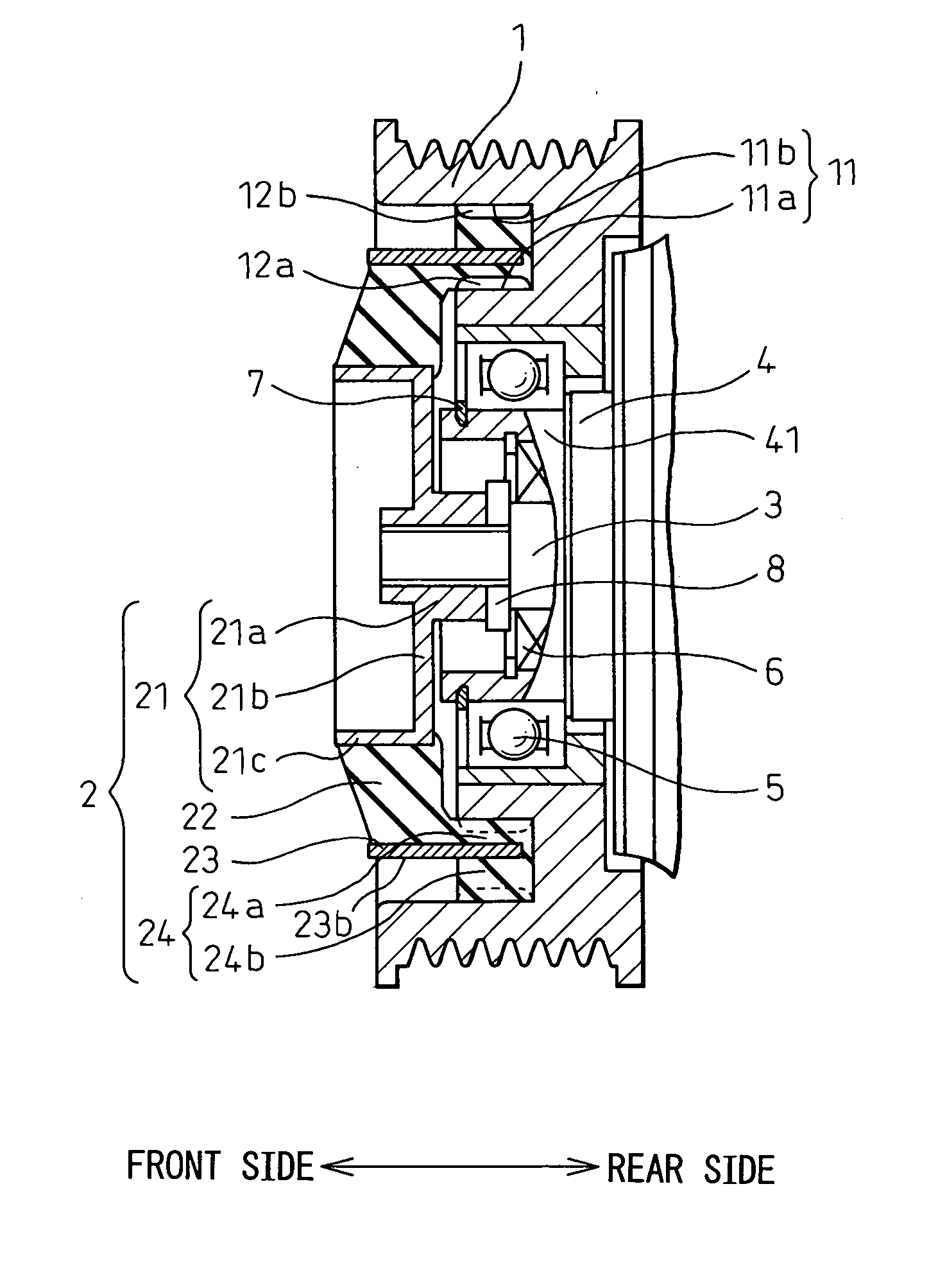
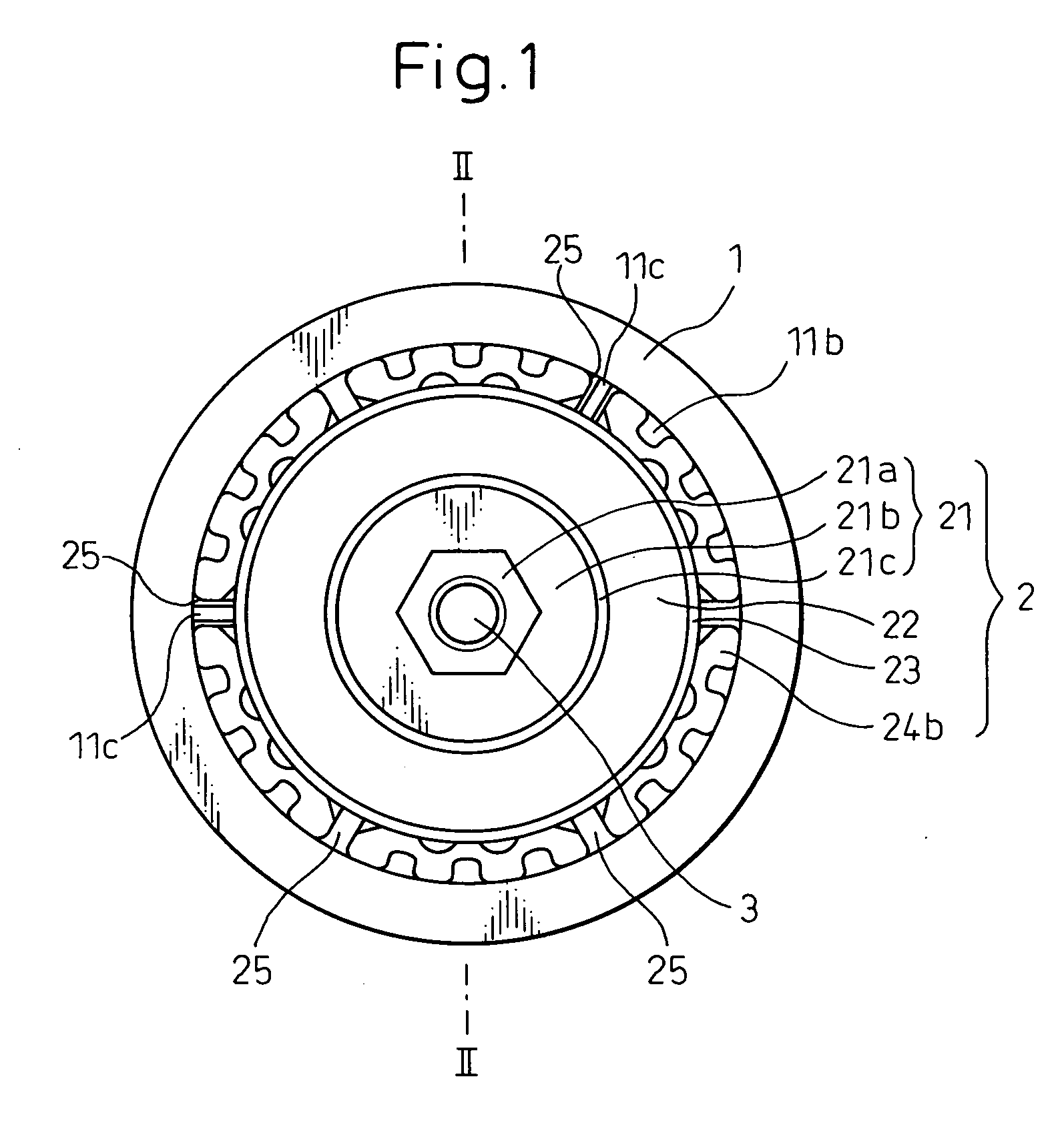
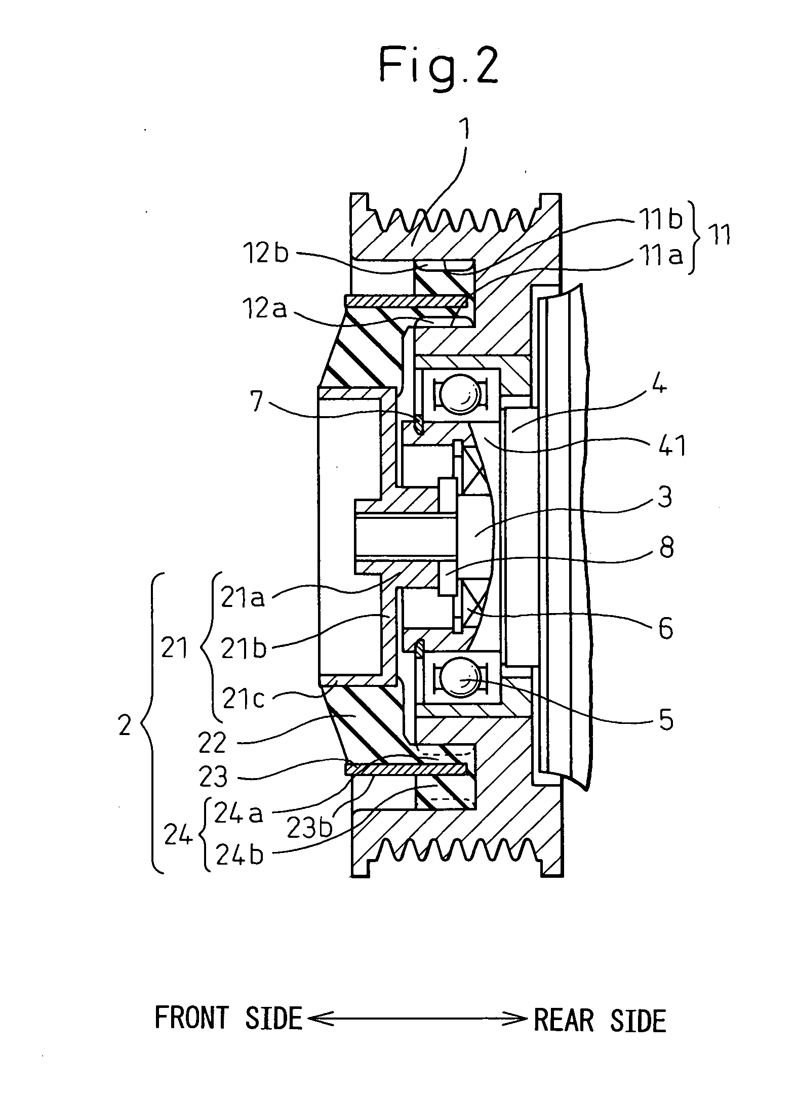
[0068] Power transmission devices according to the preferred embodiments of the invention will be hereinafter explained with reference to the accompanying drawings. The power transmission device of the invention is suitably assembled to a compressor of a car air conditioner. FIG. 1 is a front view of a power transmission device according to the invention and FIG. 2 is a sectional view taken along a line II-II in FIG. 1. The power transmission device of this invention transmits power (torque) between a pulley 1 as a driving side rotary member for acquiring power from an engine and a motor and a hub 2 as a driven side rotary member fixed to a rotary shaft 3 of the compressor. The pulley 1 and the hub 2 are arranged on the same axis.

[0069] The pulley 1 is rotatably fitted to a cylindrical portion 41 formed at one of the ends of a housing 4 of the compressor through a bearing 5. The pulley 1 is appropriately molded from a thermoplastic synthetic resin but may be formed of a metal such a...

second modified embodiment

[0090] In the second modified embodiment shown in FIG. 8B, the reinforcing portions 23a, formed in the outer hub 23 as to face outward in the radial direction, are buried into only the convex portions corresponding to the rear side among the group of the concavo-convex portions of the second hub side engagement portion 24b in the rotating direction.

third modified embodiment

[0091] In the third modified embodiment shown in FIG. 8C, the reinforcing portions 23a, formed in the outer hub 23 as to face outward in the radial direction, are buried into only the convex portions corresponding to the front side among the group of the concavo-convex portions of the second hub side engagement portion 24b in the rotating direction.

[0092] Any of these first to third modified embodiments can improve the strength of the hub side engagement portion 24.


PUM


Abstract

A power transmission device includes a pulley 1 and a hub 2 having an inner hub 21, a rubber damper 22 and an outer hub 23. A hub side engagement portion 24 formed of an elastic material and arranged either one, or both, of inner peripheral surface and outer peripheral surface of the outer hub engages with a pulley side engagement portion 12, arranged at a position corresponding to the outer hub, of the pulley in concavo-convex fitting to thereby constitute a torque transmission structure between the hub and the pulley. The hub side engagement portion and the pulley side engagement portion have a concavo-convex outer shape and mesh with each other.

Description

BACKGROUND OF THE INVENTION [0001] 1. Field of the Invention [0002] This invention relates to a power transmission device having the function of a torque limiter. More particularly, the invention relates to a power transmission device that is used when assembled into a car compressor. [0003] 2. Description of the Related Art [0004] In a power transmission device for transmitting power to a compressor in the prior art, a coupling method of a hub having a damper attenuation mechanism made of a material such as rubber and a pulley has been conducted by a method shown in FIGS. 27A and 27B. In other words, when a pulley A is made of a metal such as iron, a screw thread is formed on the pulley A and the pulley A and a hub B are coupled by a bolt C, or the like (refer to Japanese Unexamined Patent Publication No. 2001-153152). Incidentally, symbol D represents a rubber damper. [0005] In the case of a pulley A made of a material having a relatively low material strength, compared to metal, ...

Claims


Application Information

Patent Timeline
IPC IPC(8): F16H55/36F16D3/00
CPCF16D3/68F16D7/048F16H55/36F16H2055/366
Inventor NOSAKA, MICHIYASUTABUCHI, YASUOUEDA, MOTOHIKOTADA, YOSHIKINAGAE, HIROSHIYAMASHITA, MASAHIROKIDA, KOUJITANABE, MITSUHIRO
Owner DENSO CORP
Why Eureka
Try Eureka