Supercharge Your Innovation With Domain-Expert AI Agents!

Programmable logic controller programming system

a logic controller and programming system technology, applied in the direction of electric controllers, program control, electric programme control, etc., can solve the problems of time-consuming development and debugging of control programs, several drawbacks of the programming system and method,

Inactive Publication Date: 2006-04-20
DEMCO ENTERPRISES INC
View PDF23 Cites 12 Cited by
  • Summary
  • Abstract
  • Description
  • Claims
  • Application Information

AI Technical Summary

Benefits of technology

"The present invention is a method and apparatus for controlling a process using a programmable logic controller (PLC) that has multiple inputs and outputs. The PLC directs the process through signals based on input signals. It accesses an input control data element for a sequential step and an output data element for the step from an input control data table and an output data table, respectively. The PLC provides output signals at the outputs identified by the output data element to be activated for the sequential step and monitors inputs for the sequential step. The PLC performs the next step if an input signal is detected for at least one of the monitored inputs. The invention also provides a graphical user interface for programming the PLC. The interface allows a user to select inputs and outputs for each step and the PLC creates a table to record the selections. This simplifies the programming process and reduces the likelihood of errors. The technical effects of the invention include improved process control and efficiency through automation and programming flexibility."

Problems solved by technology

This programming system and method suffer from several drawbacks.
Also, even slight changes in the operating parameters of the machine require development of a new control program for the PLC.
This dependence upon familiarity with the ladder logic programming system leads to time consuming development and debugging of control programs by one having intimate knowledge of ladder logic programming.

Method used


Image

  • Programmable logic controller programming system
  • Programmable logic controller programming system
  • Programmable logic controller programming system

Examples


Embodiment Construction

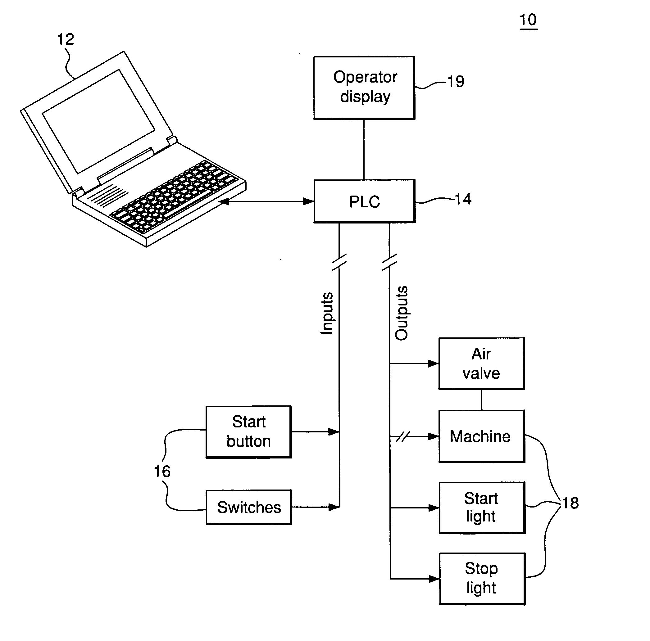
[0017] The apparatus and method for controlling a process allow the operating parameters of a programmable logic controller to be reconfigured simply by manipulating the data elements of the input control data table and output data table. No reprogramming, other than this manipulation, is required for the PLC control program, thereby relieving operators of their dependence on ladder logic programming and debugging as well as eliminating the need to order custom programmed PLCs. Further, an operator does not have to search a complex ladder logic program to identify sources of operational faults.

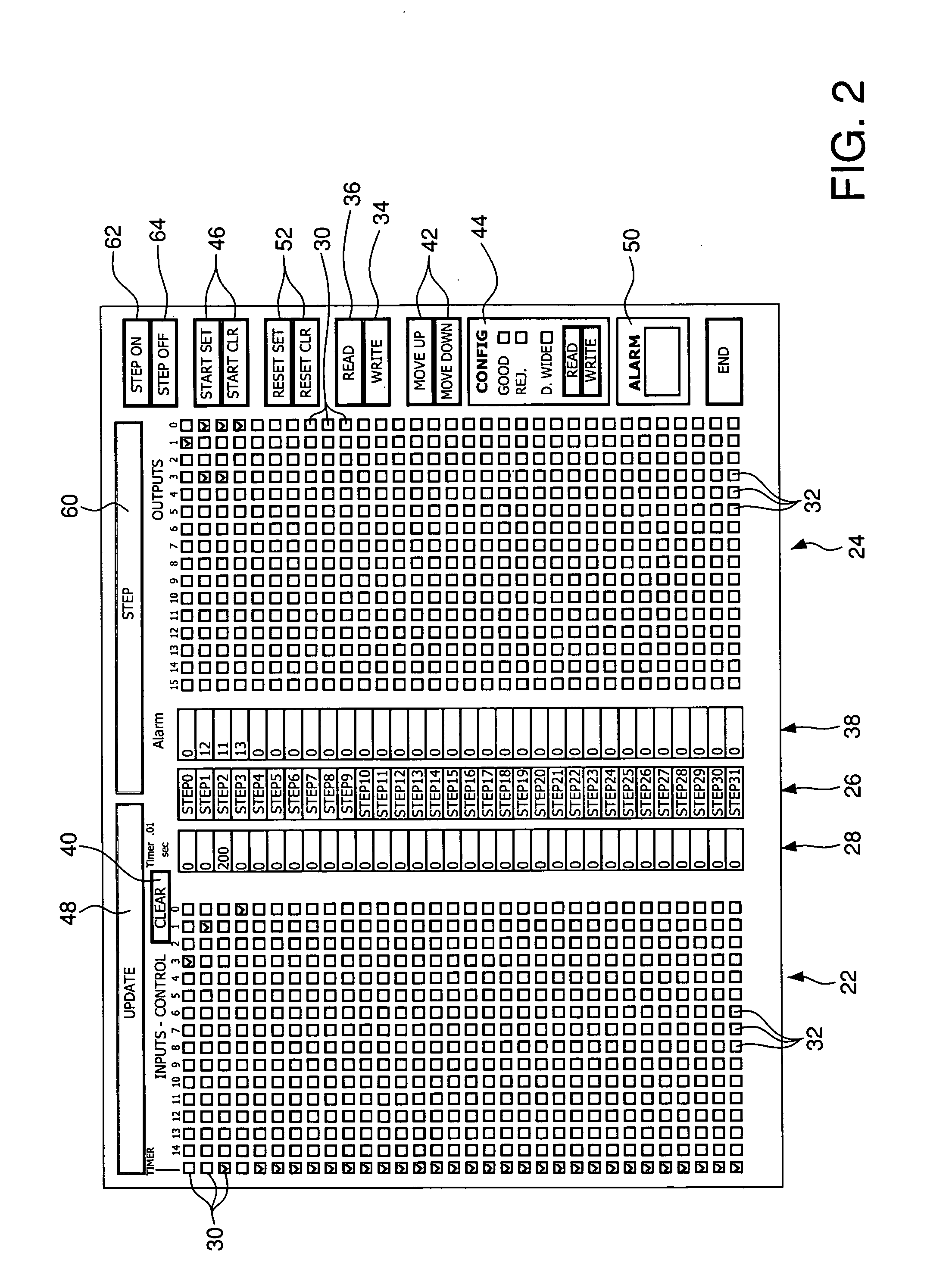
[0018] The exemplary embodiment of the present invention described herein allows for the programming of a programmable logic controller using a user friendly graphical interface without any knowledge of ladder logic programming by the programmer. Programming time is greatly reduced and the debugging process is simplified. The operating parameters of a programmable logic controller executing i...


PUM


Abstract

A programming system includes a graphical data entry user interface for a plurality of sequential steps displayed to a user on a monitor. The user selects outputs to be activated for each of the sequential steps and any inputs to be monitored or timer to be enabled for the sequential steps. The inputs, outputs, and timer enable commands, and timer values identified by the user are converted into data tables each having a plurality of data elements. Each data element corresponds to one of the sequential steps. A programmable logic controller directs a process by reading the data elements corresponding to a sequential step and, for that sequential step, activating the outputs identified by the output data element, monitoring any inputs identified by the input control data element, and enabling a timer for a selected time period if identified in the input control data element.

Description

CROSS-REFERENCE TO RELATED APPLICATION [0001] This application is divisional of U.S. patent application Ser. No. 09 / 772,493 filed Jan. 30, 2001, the entirety of which is hereby incorporated by reference herein.FIELD OF THE INVENTION [0002] The present invention relates to programmable logic controller systems, and more particularly to methods and apparatuses for programming programmable logic controllers and methods and apparatuses for directing processes through programmed programmable logic controllers. BACKGROUND OF THE INVENTION [0003] Programmable logic controllers (PLCs) are special data processors that are often used as controllers for machines in industrial processes. A PLC is typically programmed with a sequential program for controlling a machine, such as a pressing or marking machine, that continuously repeats the same motions during, for example, an automated assembly process or other manufacturing process. [0004] Each PLC operates under the control of a program stored i...

Claims


Application Information

Patent Timeline
Patent Type & Authority Applications(United States)
IPC IPC(8): G05B11/01G05B19/05G06F3/00
CPCG05B19/056G05B2219/13145Y10S715/97Y10S715/967
Inventor DUEMLER, DAVID W.
Owner DEMCO ENTERPRISES INC
Features
  • R&D
  • Intellectual Property
  • Life Sciences
  • Materials
  • Tech Scout
  • Unparalleled Data Quality
  • Higher Quality Content
  • 60% Fewer Hallucinations
Learn More