Apparatus, system, and method for automatically minimizing real-time task latency and maximizing non-real time task throughput

a real-time task and automatic minimizing technology, applied in the field of multiprocessor computing, can solve the problems of soft real-time tasks that require a very high probability of response time below the maximum threshold, serious failure of task and/or system managed by rt tasks, etc., and achieve the effect of maximizing nrt throughput and minimizing rt task latency

Active Publication Date: 2006-04-20
TWITTER INC
View PDF16 Cites 24 Cited by
  • Summary
  • Abstract
  • Description
  • Claims
  • Application Information

AI Technical Summary

Benefits of technology

[0046]FIG. 6B is a schematic flow chart diagram illustrating certain additional steps for one embodime...

Problems solved by technology

Failure to service the RT task within the threshold can cause serious failure of the task and/or systems managed by the RT task.
Soft real time tasks require a very high probability that the response time is below the maximum threshold, but not an absolute guarantee.
Failure to meet the maximum threshold for response time may result in detectable “skips” or degradation in quality, but not critical failures such as possible death.
Typically, NRT tasks are tasks that involve user interaction where long delays in response to user inputs results in a poor user experience but no loss of data, functionality, or a critical failure.
Consequently, the number of tasks managed by the OS can lengthen the task latency due to the increased overhead in handling each additional task.
Unfortunately, the RTOSs favor the RT tasks over the NRT tasks.
Consequently, a NRT task may experience poor responsiveness on an RTOS system.
Often, if the RTOS support NRT tasks, the NRT task is so delayed in responding to user inputs that the user notices a delay in response to a user-initiated action.
If NRT tasks and RT tasks are run t...

Method used


Image

  • Apparatus, system, and method for automatically minimizing real-time task latency and maximizing non-real time task throughput
  • Apparatus, system, and method for automatically minimizing real-time task latency and maximizing non-real time task throughput
  • Apparatus, system, and method for automatically minimizing real-time task latency and maximizing non-real time task throughput

Examples


Embodiment Construction

[0047] It will be readily understood that the components of the present invention, as generally described and illustrated in the Figures herein, may be arranged and designed in a wide variety of different configurations. Thus, the following more detailed description of the embodiments of the apparatus, system, and method of the present invention, as presented in the Figures, is not intended to limit the scope of the invention, as claimed, but is merely representative of selected embodiments of the invention.

[0048] Many of the functional units described in this specification have been labeled as modules, in order to more particularly emphasize their implementation independence. For example, a module may be implemented as a hardware circuit comprising custom VLSI circuits or gate arrays, off-the-shelf semiconductors such as logic chips, transistors, or other discrete components. A module may also be implemented in programmable hardware devices such as field programmable gate arrays, ...


PUM


Abstract

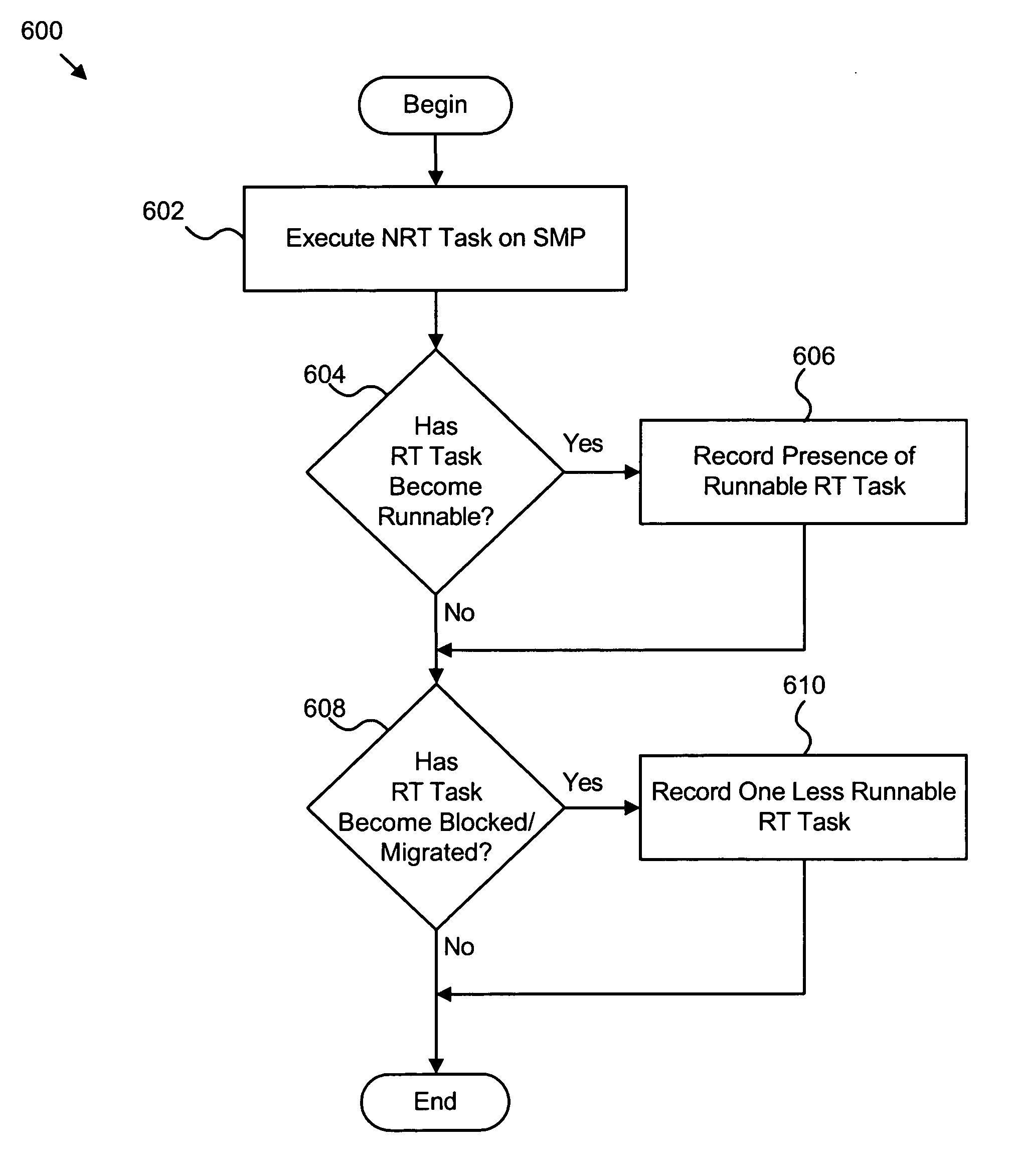
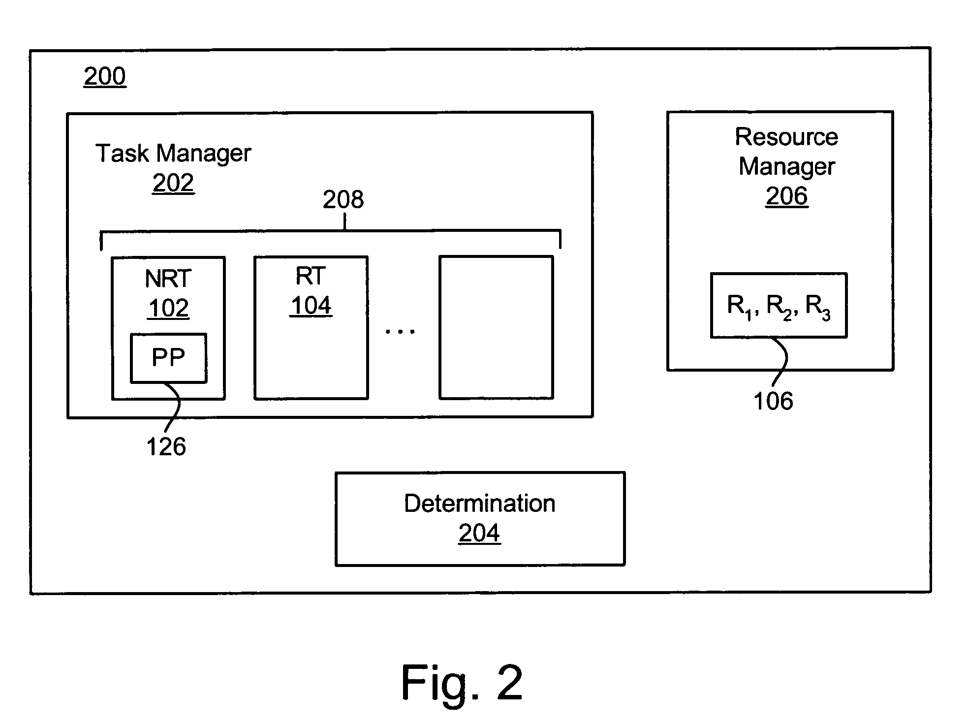
An apparatus, system, and method are provided for automatically minimizing Real-Time (RT) task latency and maximizing Non-Real Time (NRT) task throughput. The apparatus may include a task manager, a determination module, and optionally a tracking module. The task manager may execute a NRT task configured to obtain exclusive access to a resource within a multi-processor environment. The determination module identifies a RT task within the multi-processor environment that shares exclusive access to the resource with the NRT task. Optionally, the tracking module selectively executes or bypasses a preemption point associated with the NRT task in response to the RT task becoming runnable. Alternatively, the NRT task selectively executes or bypasses a predefined preemption point in response to the RT task becoming runnable. In this manner, RT tasks on any processor of the multi-processor environment meet minimum latency thresholds and NRT tasks automatically provide maximum throughput in the multi-processor environment.

Description

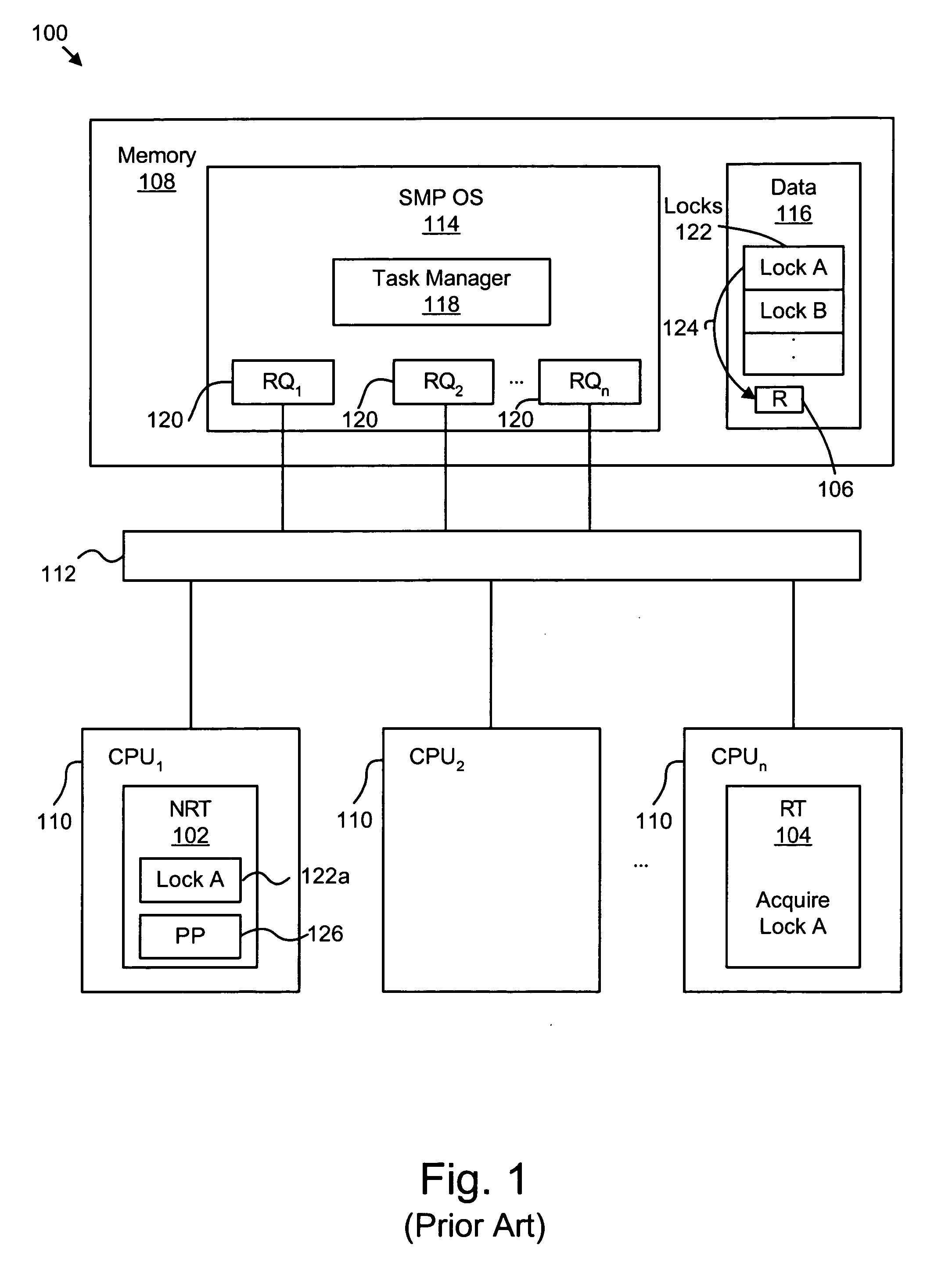
BACKGROUND OF THE INVENTION [0001] 1. Field of the Invention [0002] The invention relates to multi-processor computing. Specifically, the invention relates to apparatus, systems, and methods for automatically minimizing real-time task latency and maximizing non-real time task throughput. [0003] 2. Description of the Related Art [0004] Mainstream computer systems are currently moving from conventional single processor architectures, also known as Uniprocessor (UP), to multi-processor architectures. In particular, Symmetric Multi-Processor (SMP) architectures or environments are becoming more widely used in various fields. In an SMP environment, typically, hardware computing resources such as memory, communications bus, I / O devices, and the Operating System (OS) are shared by two or more processors. The multiple processors cooperate as peers each having an equal ability to service tasks assigned by the OS. [0005] A multi-processor environment or SMP system can be implemented with mult...

Claims


Application Information

Patent Timeline
IPC IPC(8): G06F9/46
CPCG06F9/526
Inventor MCKENNEY, PAUL EDWARD
Owner TWITTER INC
Why Eureka
Try Eureka