Method of unseating a tire

a tire and unseating technology, applied in the direction of vehicle testing, structural/machine measurement, ways, etc., can solve the problems of weak reproducibility, inability to satisfactorily reproduce, and considerable deterioration of rolling performance, so as to reduce the surface area necessary, reduce the duration of the test, and precisely measure the behavior of the tire

Inactive Publication Date: 2006-04-27
MICHELIN RECH & TECH SA
View PDF10 Cites 2 Cited by
  • Summary
  • Abstract
  • Description
  • Claims
  • Application Information

AI Technical Summary

Benefits of technology

[0026] When the steering angle is increased by steps of discrete values, it is preferable to maintain each angular value for a certain duration so as to achieve stabilization of the stresses in the contact zone between tire and roadway. Preferably, the first increase in steering angle to a value equal to an angle α0 (alpha 0) different from 0° which causes the tire to travel over the first trajectory portion formed of an arc of a circle is greater than the subsequent increases Δα (delta alpha) which correspond to fractions of the angle α0 (alpha 0). Selecting a large increase at the start of the test makes it possible to pass rapidly through a range in which unseating should not take place and thus to reduce the duration of the test. When the test is performed according to the second preferred embodiment, this marked initial increase also makes it possible to reduce the surface area necessary to perform the test: in effect, a small steering angle results in a trajectory with a large radius of curvature and consequently means that the arc of a circle traveled over by the tire has a large radius. The steering angle is then increased by smaller steps Δα (delta alpha) to obtain a more precise measurement of the behavior of the tire.
[0027] Preferably, the increases in steering angle are effected at speeds of rotation of the steering wheel of greater than 300°, and preferably greater than 500° per second, because this makes it possible to reduce the time during which the tire is under transient conditions of stress.
[0028] In order to limit discrepancies in the predetermined steering angle values, the vehicle preferably has a means for assisting in the rapid achievement of a predetermined steering angle. This may be a simple mark on the steering wheel and on the instrument panel, but it is also possible to effect measurement of the steering angle and to display the measured value in real time on the instrument panel of the vehicle. The vehicle may also be fitted with mechanical means allowing rapid, precise achievement of a given steering angle.

Problems solved by technology

The capacity of a tire to resist unseating is one of the features which is important to the safety of the users of a vehicle with tires, since unseating is associated with considerable deterioration of rolling performance.
One of the difficulties of this approach is that the results cannot be reproduced satisfactorily, due to the fact that the steering angle during the bend is not controlled.
This maneuvering latitude results in weak reproducibility.
Another drawback of the previous approach lies in its very low discriminatory capacity.
Very often, it is used as a binary test (the tire either does or does not fulfill the criterion set) and does not allow the classification of tires which have fulfilled the criterion: thus it is impossible to distinguish between two types of tires which have resisted unseating after a recommended number of runs.
Although this method solves the problem of steering angle reproducibility, it nevertheless exhibits the drawback of being limited to a single steering angle, which reduces the quantity of usable data and the precision of ranking.

Method used


Image

  • Method of unseating a tire
  • Method of unseating a tire
  • Method of unseating a tire

Examples


second embodiment

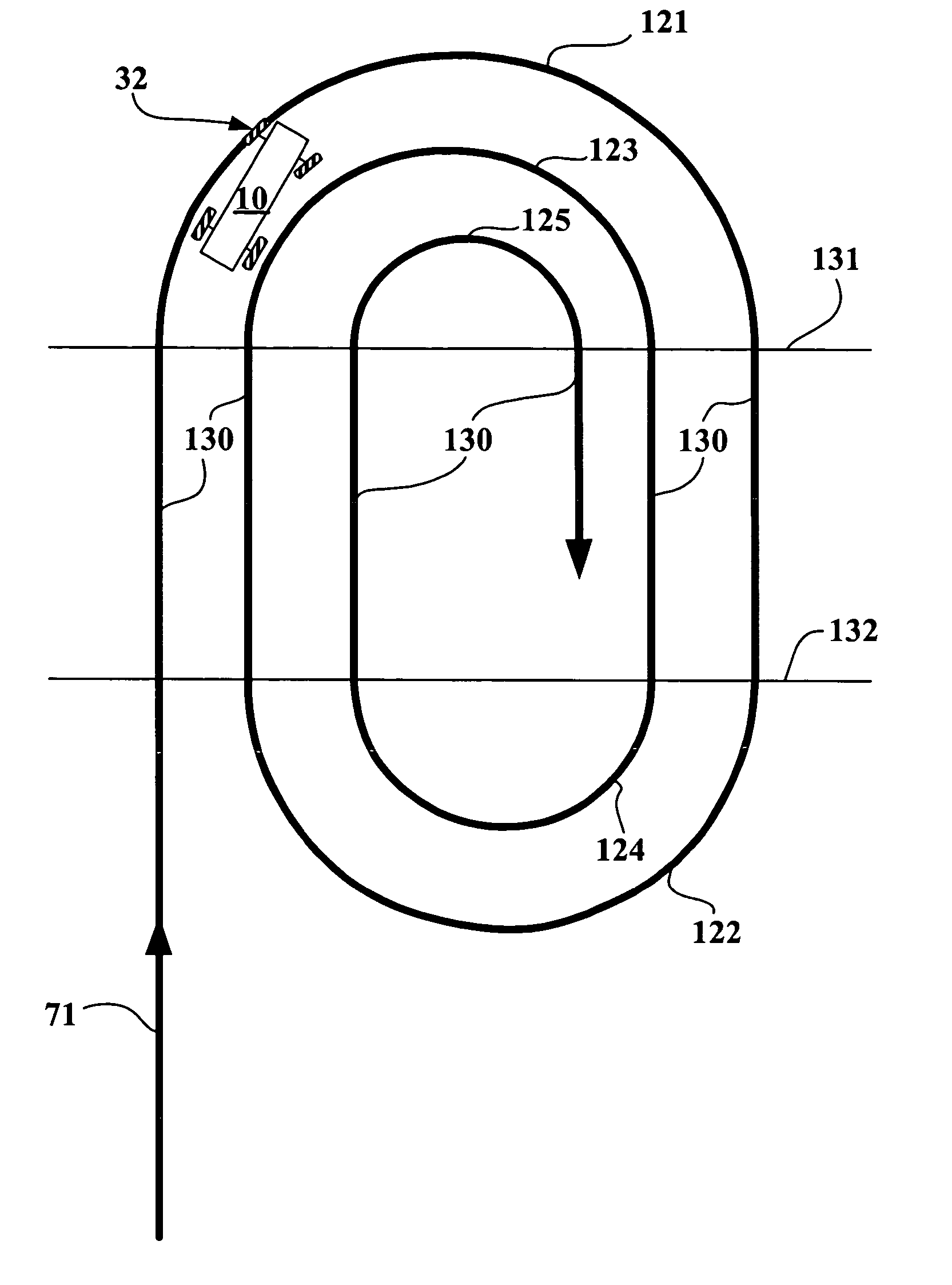
[0052]FIG. 8 shows the invention in which the trajectory 100 traveled by the tire and wheel assembly 32 until one of the two conditions (i) or (ii) is fulfilled is an uninterrupted succession of arcs of circles. As in the previous embodiment, the steering axle 21 of the vehicle 10 is equipped with a tire and wheel assembly 32 comprising the tire to be evaluated, the inflation pressure of which is zero. The vehicle starts off at the constant speed of 60 km / h along a straight line 71. Having reached point 110, the driver increases the steering angle with a speed of rotation of the steering wheel of greater than 500° per second. The test conditions (fitting of tire, direction of rotation of steering wheel) are selected such that the tire and wheel assembly 32 is located on the side of the vehicle 10 which is on the outside relative to the centre of curvature of each trajectory portion. In the example shown, the steering angle is increased in steps of discrete values: it is maintained f...

first embodiment

[0053] The principal difference relative to the first embodiment relates to the trajectory traveled by the tire and wheel assembly 32 between two trajectory portions consisting of arcs of circles. Instead of returning the vehicle 10 to the starting point, the driver immediately proceeds to increase the steering angle, which has the effect of causing the tire and wheel assembly 32 to travel over a trajectory in the form of a spiral, composed of a plurality of arcs of circles whose radii of curvature diminish progressively. The points 111 to 113 correspond to the changes in steering angle. The steering angle is increased until at least one condition selected from among the following is fulfilled: (i) the tire becomes unseated or (ii) the steering wheel of the vehicle 10 reaches its stop. The transverse acceleration of the vehicle 10 is recorded for each value of the steering angle.

[0054]FIG. 9 shows another embodiment of the invention in which two successive arcs of circles are separa...


PUM


Abstract

The resistance to unseating of at least one tire mounted on a mounting rim and inflated to a predetermined pressure is determined by mounting the tire/rim unit on a vehicle in a steering axle position. The vehicle is set in motion in a straight path and stabilized at a predetermined speed. The steering wheel is then rotated to impose a steering angle which is maintained so that the vehicle travels along a circular trajectory arc. If the tire does not unseat, increases in the steering angle are made periodically so that the vehicle travels in progressively tighter circular trajectory arcs until either the tire becomes unseated or the steering wheel reaches its terminal stop.

Description

FIELD OF THE INVENTION [0001] The present invention relates to test methods for tires. BACKGROUND OF THE INVENTION [0002]“Unseating” of a tire means at least one of the beads of the tire escaping from all or part of the seat of the rim on which the tire is mounted. The capacity of a tire to resist unseating is one of the features which is important to the safety of the users of a vehicle with tires, since unseating is associated with considerable deterioration of rolling performance. A study of the phenomenon has shown that there are two types of unseating: (1) unseating resulting from violent impacts to the sidewall or the tread of the tire, such as for example an impact against a pavement or passage of the tire over a hole in the roadway, and (2) unseating in the presence of very strong mechanical stresses such as for example during travel at high speed round a bend with a small radius of curvature, all this possibly being made worse by an inflation pressure lower than the operati...

Claims


Application Information

Patent Timeline
Patent Type & Authority Applications(United States)
IPC IPC(8): G01M17/02
CPCG01M17/02
Inventor TATRAUX-PARO, JEAN-MICHELGAUTHIER, PATRICE
Owner MICHELIN RECH & TECH SA
Why Eureka
Try Eureka