Arc-enhanced friction stir welding

a technology of friction stir welding and arc-enhanced welding, which is applied in the direction of welding equipment, manufacturing tools, non-electric welding equipment, etc., can solve the problems of rapid wear of the friction stir welding head and difficulty in achieving friction stir welding of materials with different melting points or other physical properties, and achieve the effect of less energy inpu

Active Publication Date: 2006-04-27
WISCONSIN ALUMNI RES FOUND
View PDF7 Cites 34 Cited by
  • Summary
  • Abstract
  • Description
  • Claims
  • Application Information

AI Technical Summary

Benefits of technology

[0006] In a preferred version of the invention exemplified by FIGS. 2a-2c, a welding device includes a torch 200 for supplying an electrical arc 202 to a workpiece W, and a friction stir welding head 204 which frictionally stirs the workpiece W at the location(s) at which the arc 202 is applied. The workpiece W may be a single piece of material or several adjacently situated pieces (here W1 and W2) spaced by joints J to be welded, e.g., butt joints (where the edges of the pieces abut, as shown in FIGS. 2a-2c), lap joints (where the edges of the pieces overlap), or combinations of the two (e.g., tee joints, wherein a butt joint is itself abutted by an edge of another piece of material). The torch 200 and the friction stir welding head 204 are movable with respect to the workpiece W, either by moving the workpiece W relative to the torch 200 and the friction stir welding head 204 (as by situating the workpiece W on a movable mounting bed, not shown), and / or by moving both the torch 200 and the friction stir welding head 204 relative to the workpiece W. The torch 200 and the friction stir welding head 204 thereby travel about the workpiece W to first apply the arc 202 to each location on the workpiece W at which a weld is desired, and then apply frictional stirring. Such a location may simply be a spot, or may instead be an extended line. As an example, the torch 200 may be situated adjacent the joint J of the workpiece W to apply the arc 202, and may then be moved along the joint J (as depicted in FIG. 2a). The friction stir welding head 204, which may be movable with respect to the torch 200 and which may be initially retracted away from the workpiece W (as also depicted in FIG. 2a), may then be moved into at least substantially the same plane at which the arc 202 was initially located, and may then frictionally stir the workpiece W along its joint J where the arc was applied (as depicted in FIG. 2b). The friction stir welding head 204 may then follow the torch 200 so that the locations on the workpiece W which were preheated by the arc 202 are frictionally stirred, thereby completing the weld (as depicted in FIG. 2c). The arc 202 is preferably applied at a voltage and current such that it does not melt the workpiece W, but rather plasticizes it so that less energy input is required by the friction stir welding head 204 to effect stirring. Alternatively, the arc 202 may melt the workpiece W, but in this case the arc 202 strength is preferably such that by the time the friction stir welding head 204 is applied to the arced location, the arced location will have at least partially solidified.

Problems solved by technology

While friction stir welding is a valuable welding process, particularly for soft and / or thin workpieces, it tends to suffer from the disadvantages that the friction stir welding heads rapidly wear (particularly when harder materials are being welded).
Additionally, it is often difficult to accomplish friction stir welding of materials with different melting points or other physical properties.

Method used


Image

  • Arc-enhanced friction stir welding
  • Arc-enhanced friction stir welding
  • Arc-enhanced friction stir welding

Examples


Embodiment Construction

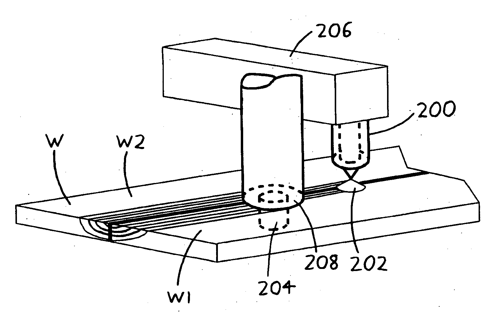
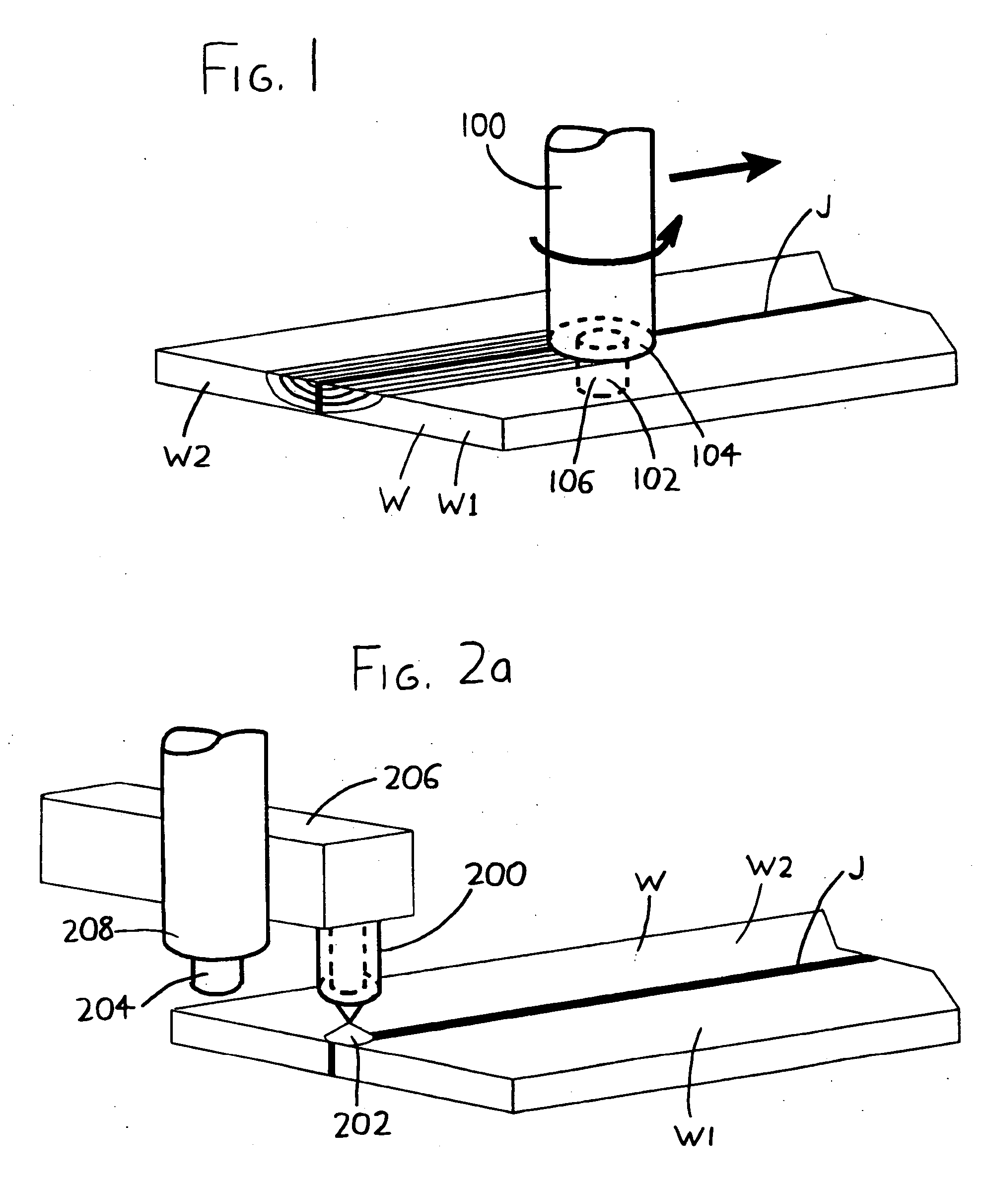
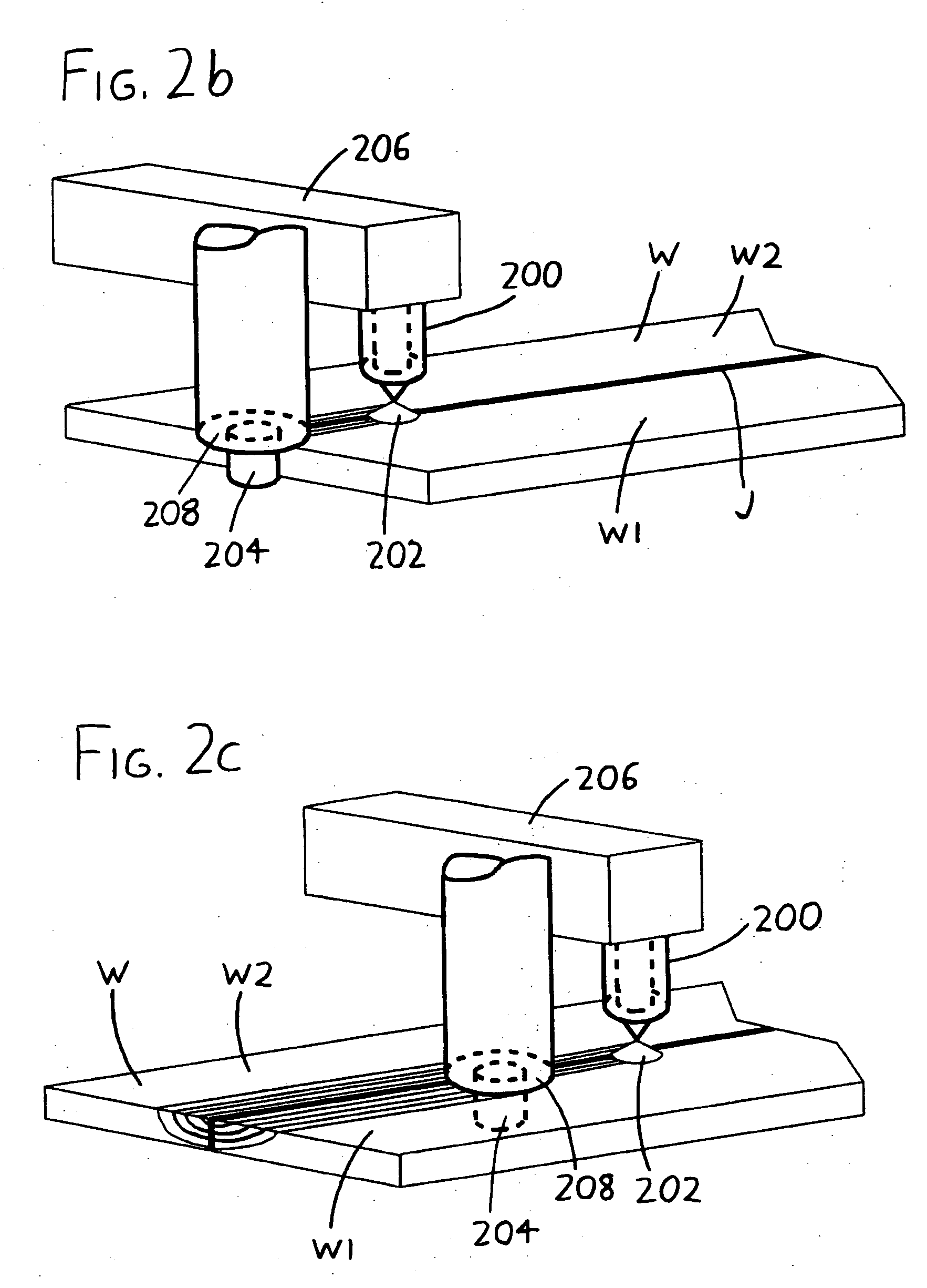
[0012] Further details regarding the exemplary versions of the invention depicted in FIGS. 2a-2c and 3 will now be provided, and the reader is encouraged to consult the foregoing Summary of the Invention if basic details are desired.

[0013] The invention is usefully implemented in automated or substantially semi-automated form, with a robotic welding unit including both the torch 200 / 300 and the friction stir welding head 204 / 304, and with a computer or other controller directing the relative motion of the workpiece W versus the torch 200 / 300 and the friction stir welding head 204 / 304 (and also directing the relative motion of the friction stir welding head 204 / 304 versus the torch 200 / 300, if any such motion is used). It should be understood that the invention may move the workpiece W with respect to the welding unit (i.e., with respect to the torch 200 / 300 and the friction stir welding head 204 / 304), and / or the welding unit may move relative to the workpiece W.

[0014] While such a...


PUM

PropertyMeasurementUnit
angleaaaaaaaaaa
arc voltageaaaaaaaaaa
areaaaaaaaaaaa

Abstract

Friction stir welding is enhanced by preheating of the workpiece with an electrical arc, such as an arc applied by a common gas-tungsten arc welding (GTAW) torch. As the arc is moved about a path on the workpiece, it preheats or partially welds the path, with the friction stir welding head following along the path to complete the weld.

Description

STATEMENT REGARDING FEDERALLY SPONSORED RESEARCH [0001] This invention was made with United States government support awarded by the National Science Foundation (NSF) in Grant No. 0098776. The United States has certain rights in this invention.FIELD OF THE INVENTION [0002] This document concerns an invention relating generally to devices and methods for friction stir welding, and more specifically to devices and methods for reducing tool wear in (and enhancing the versatility of) friction stir welding. BACKGROUND OF THE INVENTION [0003] Friction stir welding is a welding process exemplified in the accompanying FIG. 1, wherein a rotating friction stir welding tool 100 generally in the form of a cylindrical head 102 extending from a larger-diameter cylindrical shoulder 104 is rapidly rotated and contacted with a workpiece W to generate frictional heat and make the workpiece W plastic. The friction stir welding head 102 is plunged into the workpiece W, usually until its shoulder 104 ab...

Claims


Application Information

Patent Timeline
Patent Type & Authority Applications(United States)
IPC IPC(8): B23K9/00B23K20/12
CPCB23K9/167B23K20/1235B23K20/24B23K28/02
Inventor KOU, SINDOCAO, GUOPING
Owner WISCONSIN ALUMNI RES FOUND
Why Eureka
Try Eureka